The Importance of Maintaining Vacuum Pumps With Oil Changes
Maintaining vacuum pump oil and changing it regularly is very important—especially in HVAC work. Here’s why it matters and what

For those new to the field, do you find it intimidating when you have to rely on the wiring schematic on a unit to figure out what a device is or what it should do? Or do you sometimes get confused looking at all the endless lines, weird symbols, and acronyms?
I’ll be first in line to tell you I shared those same feelings when I started my HVAC career. I am going to share some basics to reading Residential Wiring schematics with you in the article. The cool thing is almost all symbols are the same across all brands, and TYPICALLY the details within the symbols have a meaning, but every now and again the symbol will be generic and you will have to add in context clues to determine what they are.
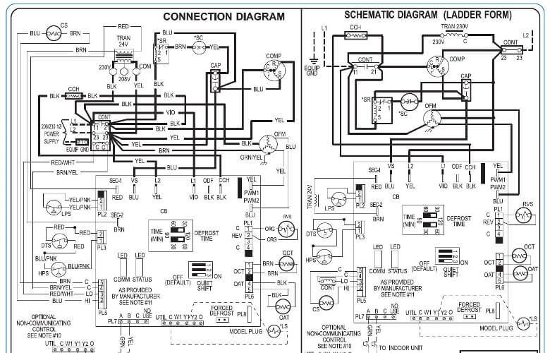
Let’s dive right in… Typical Residential Carrier wirings diagrams resemble this:
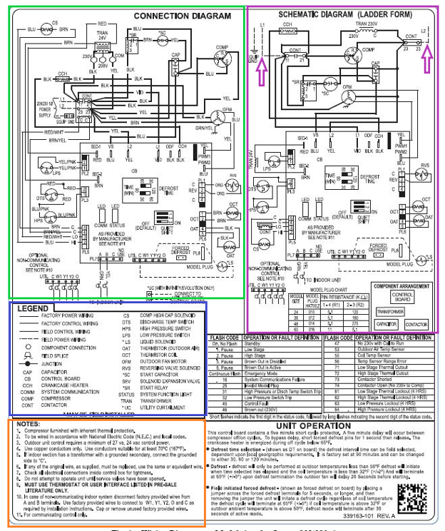
The Connection Diagram is best used when you need to know exactly where the high voltage wires are terminated, the Ladder form is best when trying to figure out how power flows from L1 to L2 through the devices- I have added two arrows to indicate L1 & L2.
Legend–ANYTIME you have an acronym (which is where a word or group of words are shortened into just a few letters) the full meaning can always be found here.
Notes– Periodically you will see “see note x” on a diagram, refer to this area for details pertaining to the area dictating the note.
Okay, now let’s break down some common symbols:
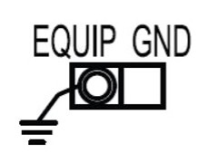
This symbol is for an equipment ground- almost any time you see three lines parallel either horizontally or vertically- they will mean earth/ ground.
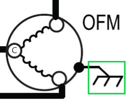
Here is an Outdoor Fan Motor where you can see it contains two windings, Start and Run. Also, in green is another symbol for ground
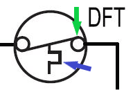
This is a DeFrost Thermostat. This zig-zag line means temperature. TYPICALLY, if you look at the right bubble on limits: if the line lands on top then it means “close on drop and open on rise” and if it’s on the bottom then it would mean “close on rise and open on drop” Remember this!
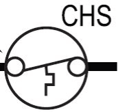
This is a CrankCase Heater- According to the description above: it will open on temperature rise.
Let’s add more to this same rule
Without looking up the acronyms I want to break these down.
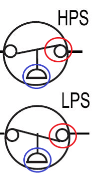
Anytime you see these half circles they mean pressure. With this known, we can now see that the top switch will “open on pressure rise”- this is a High-Pressure Switch and the bottom will “open on pressure drop”- it is a Low-Pressure Switch.
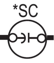
Lastly, if you see a backwards “C” next to a straight line like is presented here, then it is a capacitor. Some drawings will rotate this symbol so it will then look like a “U” and a flat line. This particular one is a Start Capacitor.
Now, keep this basic knowledge memorized and build onto it. Take a look at the close-up diagrams below and look for the symbols we just discussed and see how they interact with the electrical system.
Maintaining vacuum pump oil and changing it regularly is very important—especially in HVAC work. Here’s why it matters and what
It is very important this time of year for spring maintenance for the air conditioning system.Proper annual maintenance will help
Tip: click the images to open an enlarged view in another tab. Close the tab to return to the article.
We use cookies and other tracking technologies to collect and store information, operate our website, remember your preferences, deliver targeted ads and content, and enhance your experience. You can manage or change your cookie preferences at any time through your browser or device settings. To learn more, including how we collect, use, or disclose your information, please review our Privacy Policy and Terms of Use. By interacting with this cookie banner or accessing the site, you consent to our Privacy Policy and Terms of Use, including the arbitration provision and class action waiver.
You are leaving our site and we cannot be held responsible for the content of external websites.