Simplified Wiring Guide for R, Y1, Y2 Terminals
Tip: click the images to open an enlarged view in another tab. Close the tab to return to the article.


We have multiple articles about the defrost boards for residential and commercial units on our website and each has addressed different parts that you can read to help you diagnose what could be the problem with the system. Please follow the links at the bottom of this article to learn more about defrost boards.
When you work on a heat pump system and you want to test defrost thermostats, there are several different test procedures to test the board and sensors. Most involve “forcing” a defrost by shorting out pins on the board which will advance the time on the defrost board allowing you to test if the board is reacting to the input from the defrost thermostat or not.
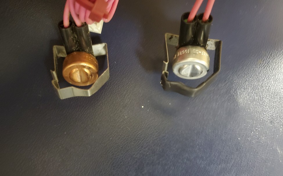
A defrost thermostat from a residential and small package product, or SPP, allows the low voltage to go from one side to the other, signaling the defrost board of 1 or 2 stage heat pumps that conditions, like the temperature, are about 32° ± 3°F. The 30, 60, 90 or 120 minutes interval depends on the model of the defrost board and how the factory or technician has set the timer. Once that time or defrost interval has elapsed, the logic of the defrost boards for Carrier, Bryant, Weathermaker, Payne and ICP heat pumps will switch the heat pump on the fly to “defrost mode” meaning the board energizes the reversing valve making the heat pump to switch to “cool” mode, the board then sends low voltage to the W2 white wire terminal signaling for the indoor unit, if equipped, to energize the heat strips. Also, the defrost board energizes the normally closed relay on the defrost board opening the electric circuit of the fan motor, thus stopping the condenser fan motor. The defrost thermostat is at the end of one of the feeder tubes and, on most units, is attached to a 3/8 copper stub tube on the bottom circuit of the condenser coil. If the heat pump has an aluminum coil, then the defrost thermostat will be made of aluminum (Do not mix a copper defrost thermostat with an aluminum coil or vice versa) See the photos below.
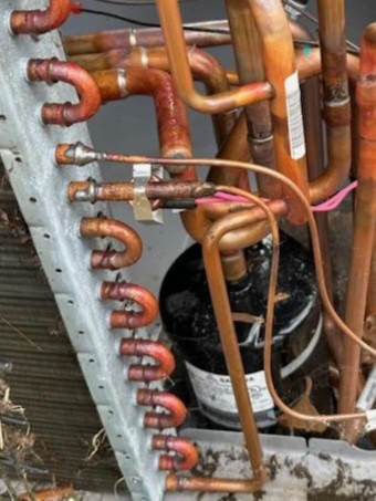
The defrost thermostat closes because of the thermally actuated switch that is inside the defrost thermostat when the conditions have changed. In this case, the stub tube no longer is 32° ± 3°F. Since the heat pump has been switched to cooling mode by the defrost board – which allows the condenser coil to get hot – the board stops the fan whenever the heat pump goes into defrost mode. This helps the heat pump to get rid of the ice faster around the condenser coil and at the stub tube where the defrost thermostat is attached.
The defrost board has been program to follow a logic. In the case of our heat pumps, that process is to terminate the defrost mode because the defrost thermostat has reached the 65° ± 5°F needed to open the internal thermally actuated switch or the defrost board has run on defrost mode for ten minutes.
This information has come from a Bryant 215B heat pump service manual.
Now that we understand what the defrost thermostat does, let’s follow the service manual on what ways we can troubleshoot the board and defrost thermostat.
First, we know that on residential and small package products the defrost thermostat closes at 32° ± 3°F and opens at 65° ± 5°F so if you find one of our heat pumps running on heat mode but has a mass of ice or frost around the coil as well as at the defrost thermostat but it is still not going on defrost mode, then you need to determine what is causing this issue using your multimeter. Start by removing the small Molex connector with the two pink wires attached to the DFT from the defrost board and check what resistance or ohms you have between those two wires. OL or infinite means the thermostat still open. If that’s the case, replace the defrost thermostat which we know, at the temperature that surrounds the defrost thermostat, should be closed.
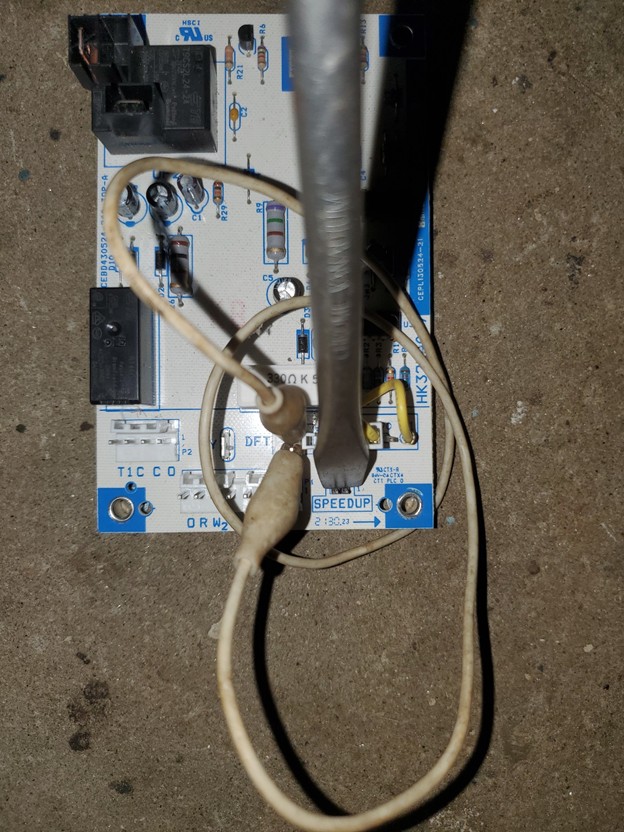
Second, we need to know if the defrost board works properly. With the same scenario, heat pump still running on heat mode, we need to test the board. With the Molex or pink wires removed from the DFT, you have two pins exposed. Attach an alligator jumper wire between the pins. Next, utilize a metal tool, like a flat screw driver, to short or connect the two speed up pins on the board. Make sure you count 5 to 7 seconds. It depends on the type of defrost board, but if you have the low voltage on the red wire from inside the unit, the logic will switch to defrost mode. When you hear the “swoosh” from the reversing valve, remove the screw driver from the speed up pins, otherwise will have a very short defrost. Once on defrost mode, you can confirm that the board is reacting to the defrost thermostat by removing the alligator jumper wire and the heat pump should switch to heat mode again.
An example below of one defrost board with the jumper on DFT terminals and with the screwdriver shorting the speed up pins. Wires were removed for clarity.
Other ways to check your defrost thermostat when you don’t have ice around it, is to run the heat pump on heat mode and carefully remove the black wire from the relay on top of the defrost board. This will stop the fan from running and the condenser coil should start frosting, making the temperature of the defrost thermostat 32° ± 3°F and checking the resistance until it closes reading 0.0 ohms indicating that is working properly. If not, it may be stuck open. Replace the thermostat. You can also remove the defrost thermostat from the heat pump and insert it into a cup with ice and water. Make sure the water its 32° ± 3°F, that way you know if it closes, the defrost works. If not, replace.
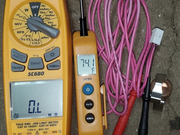
The other problem could be it’s stuck closed. You always need to know the temperature that surrounds the defrost thermostat. If it is attached to a pipe, you need to know the temperature of that pipe. Otherwise, you will be guessing. In the photo below, we have a temperature above 65° ± 5°F. We know the defrost thermostat should be open and on this defrost sensor it is open.
Please reference these articles below to learn more about defrost boards.
https://www.heatcool.com/technical-services/does-the-defrost-board-have-24vac/114474/
https://www.heatcool.com/technical-services/defrost-board-troubleshooting/139310/
https://www.heatcool.com/technical-services/where-does-the-orange-wire-go-on-a-heat-pump/74646/
https://www.heatcool.com/technical-services/schematic-reading-basics/114485/
Disclaimer: The technical statements, information and recommendations contained herein are believed to be accurate as of the date hereof, but Mingledorff’s does not make representations or warranties, express or implied, as to its accuracy, its completeness, or the results to be obtained. The information is being provided for informational purposes only and is intended for use by persons having adequate skill and expertise regarding the proper selection, use and application of the products and recommendations and at their own risk and discretion.
Tip: click the images to open an enlarged view in another tab. Close the tab to return to the article.
HVAC technicians often work in attics, rooftops, mechanical rooms, and outdoor environments where temperatures can become dangerously high. Proper hydration
Have you ever installed or started up a commercial heat pump? Did you notice there is not an “O” terminal
We use cookies and other tracking technologies to collect and store information, operate our website, remember your preferences, deliver targeted ads and content, and enhance your experience. You can manage or change your cookie preferences at any time through your browser or device settings. To learn more, including how we collect, use, or disclose your information, please review our Privacy Policy and Terms of Use. By interacting with this cookie banner or accessing the site, you consent to our Privacy Policy and Terms of Use, including the arbitration provision and class action waiver.
You are leaving our site and we cannot be held responsible for the content of external websites.