It’s important to keep HVAC Tools Calibrated
…and not just for the “by-the-book reasons Here’s why it matters in the real world: Accurate diagnostics – Gauges, thermometers, manometers,


Technical Services Manager
North Alabama District
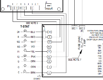
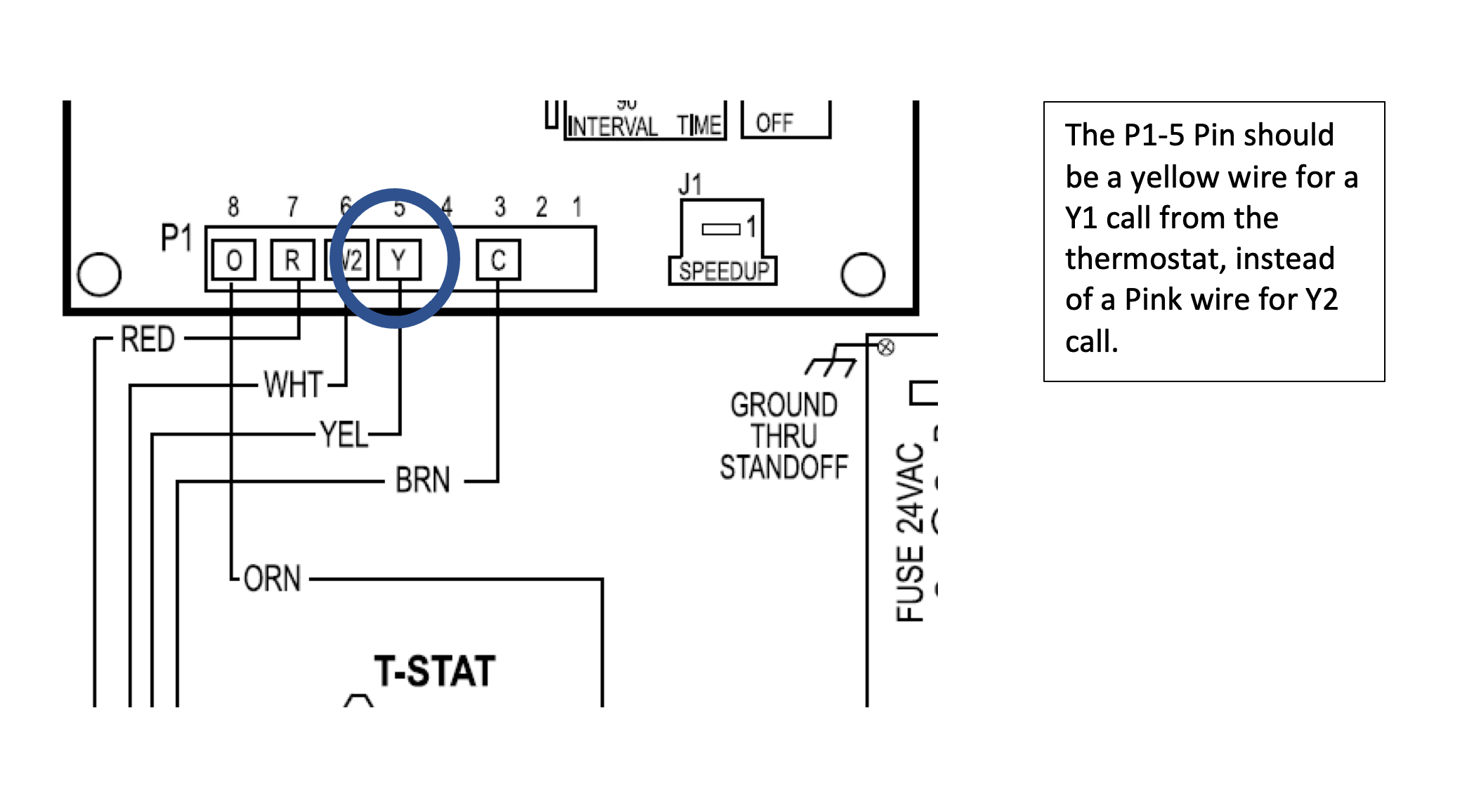
This month, I am covering a topic I have had a few calls on. 2-stage heat pump systems not cycling on until a Y2 call.
Making this correction will allow the system to operate correct and stage as needed. From the factory Wiring Diagram attached below the P1-5 Shows to be a yellow wire from the IFB for a Y1 call which will allow unit to cycle on in Low stage, and a Pink wire from the IFB to the SOL to energize the Sol for High stage. I have had a few calls from Techs were the P1-5 wire was Pink and the wires to the Sol were Yellow and Black which are not as the wiring diagram shows. The unit would only cycle on with a Y2 call due to the Y1 wire landing on the SOL.
If you correct the factory Wiring as show in wiring Diagram the unit will operate correctly as it’s designed to run. Feel free to contact your Local DSM for any questions.
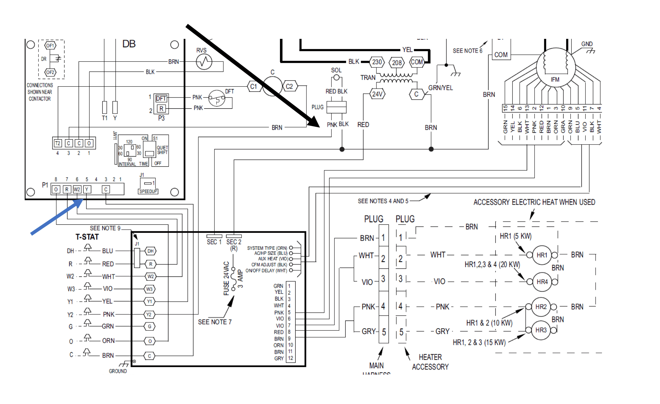

Source: Wiring Diagram is from the factory Installation Book which can be downloaded RC Mobile Tech App or hvacpartners.com
…and not just for the “by-the-book reasons Here’s why it matters in the real world: Accurate diagnostics – Gauges, thermometers, manometers,
This new unit is a noncommunicating variable 5 speed performance line heat pump with InteliSense technology, 19 seer2. Sizes range
When you get a new VFD drive and want to install it and you see that the other one was
We use cookies and other tracking technologies to collect and store information, operate our website, remember your preferences, deliver targeted ads and content, and enhance your experience. You can manage or change your cookie preferences at any time through your browser or device settings. To learn more, including how we collect, use, or disclose your information, please review our Privacy Policy and Terms of Use. By interacting with this cookie banner or accessing the site, you consent to our Privacy Policy and Terms of Use, including the arbitration provision and class action waiver.