It’s important to keep HVAC Tools Calibrated
…and not just for the “by-the-book reasons Here’s why it matters in the real world: Accurate diagnostics – Gauges, thermometers, manometers,


VRF Quality Assurance Manager
Gulf Coast District
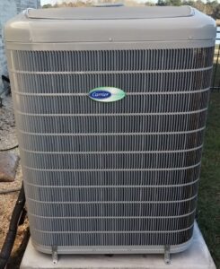
When I first learned about Carrier Infinity and Bryant Evolution systems, the idea of communication seemed like such a foreign concept from what I had been taught. It added a new element to troubleshooting that I had not learned in all my previous experience working on basic controls in mostly residential and light commercial applications. Carrier and Bryant communicating systems are different from all of it. Every control component has a voice, speaking a programmed language of binary ones and zeros, working in concert for the common goal of ideal comfort and full customization of the environment for the user, while always providing superior energy efficiency.
When I explained this to homeowners, I compared it to a perpetual boardroom meeting. The User Interface is the chair, taking in all the information from the inside and outside directors, interpreting the data, and ensuring that the meeting always runs smoothly. This analogy also works well when there are communication issues. For example, if one of the directors starts yelling or speaking nonsense, then the chair cannot hear what the other directors have to say. Resolving the issue means diagnosing what went wrong and how to re-establish good communication across the board.
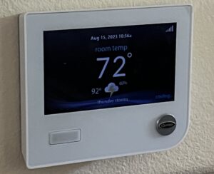
The heart and mind of all communication is the User Interface, nicknamed the UI. It is a smart TSTAT, which means that not only is it programmable, but it also learns the requirements of the user over time, and how to achieve this in the most efficient manner possible. It does this by monitoring outdoor ambient temperatures and indoor humidity to know how fast it needs to run the system to achieve the homeowner’s desired setpoints.
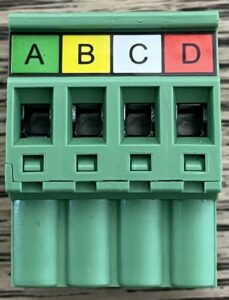
The basis of all Carrier and Bryant communication is the control wiring. Kept simple, they are ABCD. Terminals A (green) and B (yellow) provide a circuit for communication, while C (white) and D (red) are the 24VAC common and power respectively. In early generation equipment one transformer located at the indoor furnace or fancoil provided power to all controls in the system. Modern versions utilize transformers at the indoor and outdoor equipment. The indoor unit provides power to the UI, any zoning controls, and possibly a NIM (Network Interface Module), when required.
A Network Interface Module is used as an intermediary control. Infinity and Evolution fancoil control boards do not have a Y2 terminal on the analog control lugs, therefore a NIM is required when using a non-communicating two stage outdoor unit. Furnaces do have a Y2 terminal, so they do not require a NIM. It is necessary to use a NIM when connecting basic Infinity and Evolution systems to an ERV (Energy Recovery Ventilator). A NIM is not required for an ERV if the system is zoned, as the zone Damper Control Module has a connection built in.
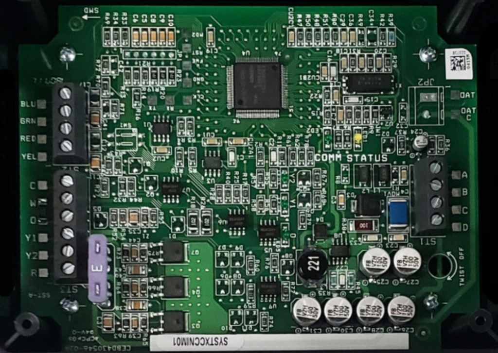
The main controls that require the AB communication wiring are the UI, the indoor furnace or fancoil, and the outdoor unit. Zone Damper Control Modules also require ABCD wiring, as well as Smart Sensor zone controls. Fancoil and furnace control boards communicate with the variable speed ECM (Electronically Commutated Motor) blower motors and provide RPM and static pressure data to the UI. If smart heat strips are used then the KW output is identified by the fancoil boards by way of a unique resistor, read by the UI through the indoor board. If basic heat strips are used, they must be identified at the time of installation.
Early generations 16, 19, and 21 SEER two speed unit control boards required power from the indoor transformer, using AB and CD connections, and communicated measured inputs, such as outdoor temperature, liquid line coil
temperature, and line voltage, to the UI. Later generation 16 and 19 SEER two speed units added a transformer and omitted CD from their control wiring.
All legacy user interface UID01 models A-D, and Z (for zoning) were compatible with any communicating 1 or 2 stage equipment. All touchscreen models are backwards compatible to all Infinity and Evolution equipment.
The Carrier Infinity GREENSPEED and Bryant Evolution EXTREME 20 SEER units were the first to have true variable speed compressors with a range from 40% capacity to 100% using a VFD (Variable Frequency Drive) inverter board. These VFDs take high voltage single phase power and invert it to three phase DC, then invert it again to three phase AC power (with the bottom half of the sine wave cut off). The variable speed is achieved by adjusting the hertz to the compressor. They use a basic 24 VAC transformer for power to the control board instead of being powered by the inverter, and only require AB wiring for communication to the UI. They communicate with the inverter board and have the same inputs as the 18 and 19 SEER units.
The UID01 control model V was the only legacy version that had the capability to drive a 20 SEER variable speed unit. All touchscreen UI models A-C are compatible.
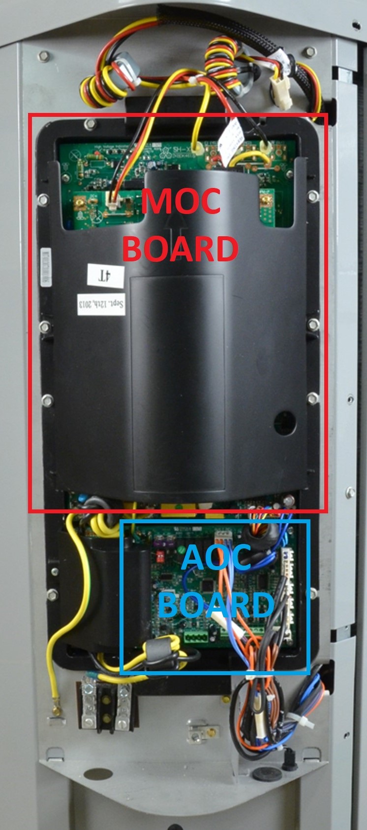
The 18/19 SEER five speed outdoor AOC (Application Operational Control) is powered from and communicates with the MOC (Motor Operational Control), nicknamed the inverter. These MOC boards take high voltage single phase AC power and invert it to three phase DC, which drives the condenser fan motor and uses PWM (Pulse Width Modulation) to gently change between stages in the 5 speed compressor. The MOC monitors temperature, current, status of the compressor, outdoor fan, and the inverter and communicates this to the AOC, which then sends all the information to the UI. These units have the same outdoor ambient, liquid line coil, and line voltage measurements as the 16-21 SEER two speed units, but have added discharge temperature, suction temperature, and suction pressure. The capacity for each model ranges from 25% in 1st stage to 100% in 5th stage.
There are no legacy Controllers that will work on the 5 speed equipment. The touchscreen UI model A had to be at least version 11 to work with these units, and version 12 was required for the 13000 btu unit. All touchscreen UI models B or C are compatible.
The most current 24/26 SEER GREENSPEED and EXTREME units work much the same as the first generation, except for a few upgrades. They now have a capacity range from 25% to 100% and have added a discharge pressure measurement to the ensemble for more protection and adjustment ability. Also, they provide a basic 24 VAC transformer for power to the control board and have added a communicating Bluetooth Module for the purpose of monitoring and updating the unit components through a phone app. Updating is required at the time of system commissioning and during any service or maintenance to ensure the unit is working at peak ability. It is imperative that all technicians have the Carrier Service Tech App, which is an extension of HVAC Partners, so they can connect to these units via Bluetooth for monitoring performance and updating.
Touchscreen model B controllers must be version 3.0 firmware or higher to drive these units. All model C controllers are compatible.
All outdoor units and furnaces have a model plug, also known as a personality plug, which identifies the unit and tonnage to the UI. Model plugs consist of two resistors of varying ohm values to provide a unique identification. The original control boards on all outdoor units, furnaces, and fancoil boards have their model and serial numbers burned into them at the factory.
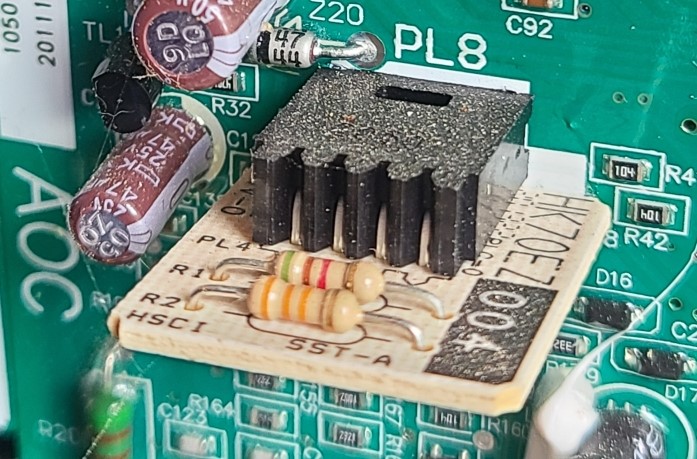
This information is lost if these boards are replaced. Fancoils boards do not have model plugs and require set up of the correct model during the re-installation at the UI, which must be done every time a communicating component is replaced throughout the system.
Look out for “Communication Is Key – Part 2” in next month’s newsletter where we will take this knowledge and focus on troubleshooting communication problems when they arise. In the meantime, check out our archives link below for the article by Jonathon Pullen titled: “What We Have is a Failure to Communicate”.
Disclaimer: The technical statements, information and recommendations contained herein are believed to be accurate as of the date hereof, but Mingledorff’s does not make representations or warranties, express or implied, as to its accuracy, its completeness, or the results to be obtained. The information is being provided for informational purposes only and is intended for use by persons having adequate skill and expertise regarding the proper selection, use and application of the products and recommendations and at their own risk and discretion.
…and not just for the “by-the-book reasons Here’s why it matters in the real world: Accurate diagnostics – Gauges, thermometers, manometers,
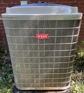
This new unit is a noncommunicating variable 5 speed performance line heat pump with InteliSense technology, 19 seer2. Sizes range
When you get a new VFD drive and want to install it and you see that the other one was
We use cookies and other tracking technologies to collect and store information, operate our website, remember your preferences, deliver targeted ads and content, and enhance your experience. You can manage or change your cookie preferences at any time through your browser or device settings. To learn more, including how we collect, use, or disclose your information, please review our Privacy Policy and Terms of Use. By interacting with this cookie banner or accessing the site, you consent to our Privacy Policy and Terms of Use, including the arbitration provision and class action waiver.