Brazing


Brazing is the process of joining two metals together without the wick effect that solder has.


It consists of two similar metals or dissimilar metals being joined by a brazing rod that melts before the metal being joined will. This will help assist in the bonding process. You can butt the two pieces together and braze them and it will be stronger than a soldered joint. The copper pipes can get red and silver solder will already be melted at this point.


Now a few other terms we must be aware of:


Liquidous temperature is the lowest temperature at which a metal is liquid. Solidus temperature is the highest temperature at which the metal is completely solid.


The temperature at which metal melts is called its melting point.


Brazing uses a higher temperature to melt the rods than soldering. Gas torches such as MAPP gas or oxy acetylene could be used depending on the environment and the size of pipe. MAPP gas works well in non-windy areas for up to ¾ inch pipe. Anything larger than that would push the limits of the heat.


In brazing, the components that make up the rods is determined by the metals you want to join. For the HVACR industry, we typically use silver solder containing different percentages of silver. This will determine the fluidity of the rod on the metal being joined, the cleanliness of the joint for aesthetics, and the strength of the joint.


Flux can come in various forms such as a paste or a coating on the rods. In the example for the HVACR purposes we will use 15% silver solder. An example composition of 15% Silver Solder is: 15% Silver, 80% Copper, 5% Phosphorous. In joining copper to copper, none of these phosphorus/silver/copper rods need flux or would even benefit from it. The phosphorus allows the rod to self-flux on copper. So, if you use the silver solder it has phosphorus in it and does not need flux. It is the flux!


Example: Two pipes cleaned and placed inside a coupling. Heat the pipes until the 15 percent silver solder melts and spreads smoothly along the metal joint between the pipe and the coupling. Then do the other pipe at the joint at the coupling as well. Then stop and allow to cool. Or use a wet rag to cool it down.

Round 2 terminal capacitor
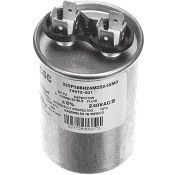
Silver cylindrical electrical capacitor with two metal terminals on top and a labeled body

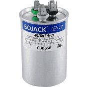
Round 3 Terminal Dual Capacitor

Silver BOJACK capacitor with blue label and metal terminals on top

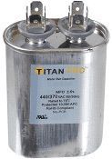
Oval Capacitor

Silver Titan capacitor with two top terminals and black label on a white background
Three-terminal metal battery with three black-capped posts on a white background

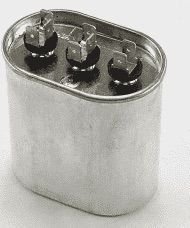
Oval Dual Capacitor

Start Capacitor - Black
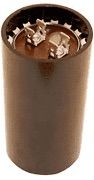
Brown cylindrical trash can filled with crumpled paper and cardboard scraps

Start Capacitor - Brown

Anthony Coker

Technical Services Manager North Georgia District

June 2, 2022

Condensate Pump Replacement

We are finding ourselves with more and more VRF components that will require maintenance periodically. Example: a 40VMF


Below are the procedures of handling one of the components mentioned above. As always, please take your time and use precautions in all work you perform.


12 Steps to replace a Condensate Pump on a 40VMF


1) This is the location of the condensate pump in relation to the control compartment


Step 1


2) Remove all screws from the four corners indicated by the arrows


Step 2


3) Remove the 3 screws to remove wire routing cover.


Step 3


4) Remove the felt tape covering the wire route


Step 4


5) Trace the pump high voltage wiring harness to the control compartment


Step 5


6) Unplug the 2 black wire connectors from the pump connector on the control board and unscrew the green ground wire from the control compartment


Step 6


7) Trace out the pump float alarm cable. Notice that it runs under the control compartment and will require taking the control compartment screws out. Let it hang down so you can access the wire all the way over to the wire bundle on the right side of the control compartment.


Step 7


8) To remove the control compartment first cut the wire tie holding the wire bundle together.


Step 8


9) Next unplug the red and black 2 wire plug from the water connector on the control board


Step 9


10) Once you have both cables disconnected remove them from the wire route in the bottom of the foam drain pan.


Step 10


11) Next you pull the drain pan down about 2 to 3 inches all the way around the unit. You will then be able to pull the condensate pump side down about 10 inches.


Step 11


12) You will then be able to access the pump Assembly which can now be removed by removing the 3 mounting screws.


Step 12


To complete the replacement, install the new condensate pump assembly and reverse the previous steps. 


More to Explore

September 16, 2026
Disclaimer: The technical statements, information and recommendations contained herein are believed to be accurate as of the date hereof, but Mingledorff’s does not make representations or warranties, express or implied, as to its accuracy, its completeness, or the results to be obtained. The information is being provided for informational purposes only and is intended for use by persons having adequate skill and expertise regarding the proper selection, use and application of the products and recommendations and at their own risk and discretion. 
By Jesse Van Atta September 16, 2026
Disclaimer: The technical statements, information and recommendations contained herein are believed to be accurate as of the date hereof, but Mingledorff’s does not make representations or warranties, express or implied, as to its accuracy, its completeness, or the results to be obtained. The information is being provided for informational purposes only and is intended for use by persons having adequate skill and expertise regarding the proper selection, use and application of the products and recommendations and at their own risk and discretion.