It is a good practice to make sure all of your dip switches are set to the factory position on all of your flow selector boxes during installation. If the dip switches are not set in the factory position you will have L11 and E17 error codes to follow. You can verify the factory dip switch settings by looking at access door on the flow selector box. The L11 and E17 error codes can also be caused by wiring issues, good wiring practices can prevent having problems.


Changing dip switches on your flow selectors is not necessary because all of your flow selector addresses and port numbers are set using and codes 00FE and 0105 on your thermostat. Making sure your flow selector address and your flow selector port address is correct will make the start up process much easier. If care is taken and you have a good understanding of the wiring and installation of a VRF system the start up process can be close to seamless.


L11- Detected indoor unit address, Flow selector unit not connected.


E17- Communication trouble between indoor unit and flow selector unit.

Once you have logged in, you will need to save the equipment current configurations by choosing: “SAVE CONFIGS TO A FILE”. Align the arrow on the SAVE CONFIGS TO FILE option and press ENTER. Then press ENTER to make the STOP flash, use the UP or DOWN arrows to change the STOP to START and press ENTER. Once this is done, Choose Option 5 to UPGRADE SOFTWARE. Then scroll down to “FIND APPLICATION FILE” and press ENTER to change NO to YES.
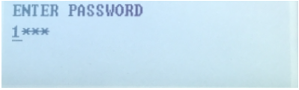
Screen shows “ENTER PASSWORD” with masked input, “1***” beneath it.

Then press ENTER to choose the USB Product Folders:
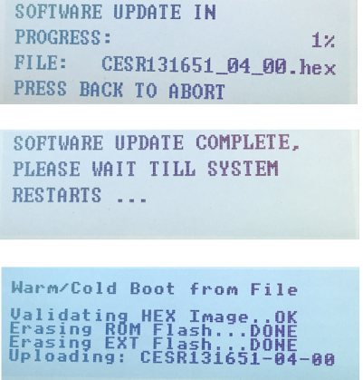
Software update screens showing firmware progress, complete message, and boot validation text on a device display

Then select the Product Software: Once selected press ENTER.
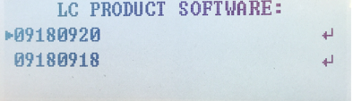
Blue monochrome LCD display reading “LC PRODUCT SOFTWARE:” with two lines of numbers beneath.

Austin Caldwell

Technical Services Manager North Georgia District

October 20, 2023

Customer States the Unit Won’t Start

This phrase can be an assortment of items on our 48TC package units. After the inspection of the unit, you see the charge is okay, No broken belts and all main voltage is present. Now after bumping the contactors, it shows everything is operational. It is determined we have an electrical issue which for most technicians not a strong suit.


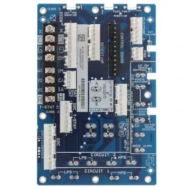
We are talking today on our electrical mechanical board shown below. Once you know the inside working, this board is very easy to master. The First step after verifying you have a call for cooling. The unit runs through the unit shutdowns. These are on the right side of the board they consist of the Smole and Remote shutdowns. If those are good, then it will send power through plug 1 on the Econ plug. Then it comes back through at 2 on the Econ plug. This is a 24-volt signal. Once verified there it goes to jumpers 6 and 7 if there is no reheat on the machine. If it is present runs through terminals 5 and 6 on single compressor units. Terminals 7 and 8 for dual compressor units. Once it passes through it will start the fan. This will then go from terminal 6 goes into terminal 4 on the compressor plug. This runs through the high and low-pressure safety. Once cleared there it goes out terminal 6 to the fan-providing switch mounted on the squirrel cage of the blower. This is closed the compressor will start.

With the knowledge now of this board. When you run into a unit not working the wiring schematic will not be as daunting to negotiate. This style control is the most common you run into on the 48tc units. But this is also a common board in multiple carrier package units ranging from 3 tons to 20 tons.

Blue electronic circuit board with chips, connectors, and labeled components on a white background

Disclaimer: The technical statements, information and recommendations contained herein are believed to be accurate as of the date hereof, but Mingledorff’s does not make representations or warranties, express or implied, as to its accuracy, its completeness, or the results to be obtained. The information is being provided for informational purposes only and is intended for use by persons having adequate skill and expertise regarding the proper selection, use and application of the products and recommendations and at their own risk and discretion.


More to Explore

September 16, 2026
Disclaimer: The technical statements, information and recommendations contained herein are believed to be accurate as of the date hereof, but Mingledorff’s does not make representations or warranties, express or implied, as to its accuracy, its completeness, or the results to be obtained. The information is being provided for informational purposes only and is intended for use by persons having adequate skill and expertise regarding the proper selection, use and application of the products and recommendations and at their own risk and discretion. 
By Jesse Van Atta September 16, 2026
Disclaimer: The technical statements, information and recommendations contained herein are believed to be accurate as of the date hereof, but Mingledorff’s does not make representations or warranties, express or implied, as to its accuracy, its completeness, or the results to be obtained. The information is being provided for informational purposes only and is intended for use by persons having adequate skill and expertise regarding the proper selection, use and application of the products and recommendations and at their own risk and discretion.