ICP Furnace Showing 80% Limit Fault
Most gas furnaces have several safety limits, main limits, roll-outs, 80%’s will have a DSS (Daft Safety Switch) These safety


This article is in reference to residential HVAC equipment but can apply elsewhere.
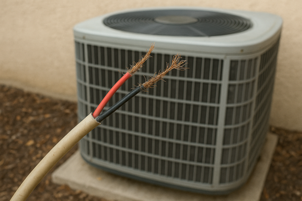
You would think that a broken wire to an outdoor unit would be easy to find, right? Well, it all depends how you troubleshoot and how you analyze the results of your troubleshooting.
HVAC technicians know that it takes two (24VAC) wires to energize standard HVAC Parts (contactors, T-stats, relays, etc.). In layman’s terms: one wire is a “power wire” which is “sending” voltage to a device; while the other wire is the “return wire” AKA: “Common Wire” that completes the loop back to the power source [the transformer].
If you were to remove or break the common wire to a device, such as an outdoor unit what would happen?
Great question! If a thermostat were to connect R to Y and R to O, then 24VAC should be sent to the outdoor unit. As 24vac on Y comes into the unit, it will pass through all the safety switches and land on the contactor; at the same time 24vac on the O wire will be sent out and fed to the reversing valve coil. If the common wire is broken from the indoor unit to the outdoor unit, then these devices will not do anything. They will sit there looking and acting deenergized.
Let’s run through a simple cooling scenario. Typical heat pump HVAC systems supply 24 VAC signals to Y for the main call and O in cooling mode to engage the reversing valve.
As a technician, when you check the contactor and reversing-valve coil wires for VAC to ground, you will have 24vac. If you check your common wire at the outdoor unit to ground, you will also have 24vac. STRANGE, right?
Why is this? Why would the Y and O wires have 24VAC, AND the common wire have 24VAC when these devices are deenergized?
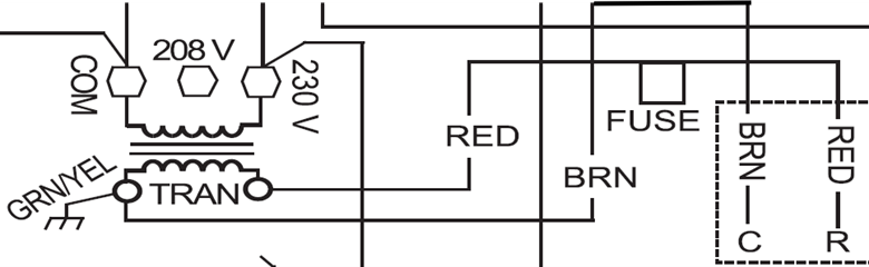
When looking at most control schematics, notice that the “return wire”, otherwise known as Common, is also connected to ground at the transformer. If this common wire from the indoor to outdoor unit is broken, the electrical current cannot make a full connection which results in an incomplete path for the voltage/amps. When checking for voltage on (Y, O, and Common) to ground, your meter is showing Voltage “Potential” to ground. This is due to the connection of the Common wire at the transformer to ground. Under normal circumstances, if the common wire were not broken, a reading of Ø Zero VAC would be read from common to ground. This proves that common and ground are tied together at the indoor transformer, and function as one single connection. This too can be said if the common wire at the outdoor unit were to be connected to ground, as it would then complete the electrical path through the ground circuit. Bear in mind this is not for a permanent repair but merely just for testing.
Remember, checking for voltage AC to ground is not the same as checking AC to Common. Always check to common, not ground.
Disclaimer: The technical statements, information and recommendations contained herein are believed to be accurate as of the date hereof, but Mingledorff’s does not make representations or warranties, express or implied, as to its accuracy, its completeness, or the results to be obtained. The information is being provided for informational purposes only and is intended for use by persons having adequate skill and expertise regarding the proper selection, use and application of the products and recommendations and at their own risk and discretion.
Most gas furnaces have several safety limits, main limits, roll-outs, 80%’s will have a DSS (Daft Safety Switch) These safety
This article is in reference to Residential Heat Pumps. Everyone in the HVAC industry knows that the indoor TXV
Compressors are the heart of the refrigeration system. It creates the pressure difference to move the refrigerant through the system.