
It is a good practice to make sure all of your dip switches are set to the factory position on all of your flow selector boxes during installation. If the dip switches are not set in the factory position you will have L11 and E17 error codes to follow. You can verify the factory dip switch settings by looking at access door on the flow selector box. The L11 and E17 error codes can also be caused by wiring issues, good wiring practices can prevent having problems.
Changing dip switches on your flow selectors is not necessary because all of your flow selector addresses and port numbers are set using and codes 00FE and 0105 on your thermostat. Making sure your flow selector address and your flow selector port address is correct will make the start up process much easier. If care is taken and you have a good understanding of the wiring and installation of a VRF system the start up process can be close to seamless.
L11- Detected indoor unit address, Flow selector unit not connected.
E17- Communication trouble between indoor unit and flow selector unit.
December 17, 2024
Hall Effect Switch Troubleshooting and Helpful IGC Codes
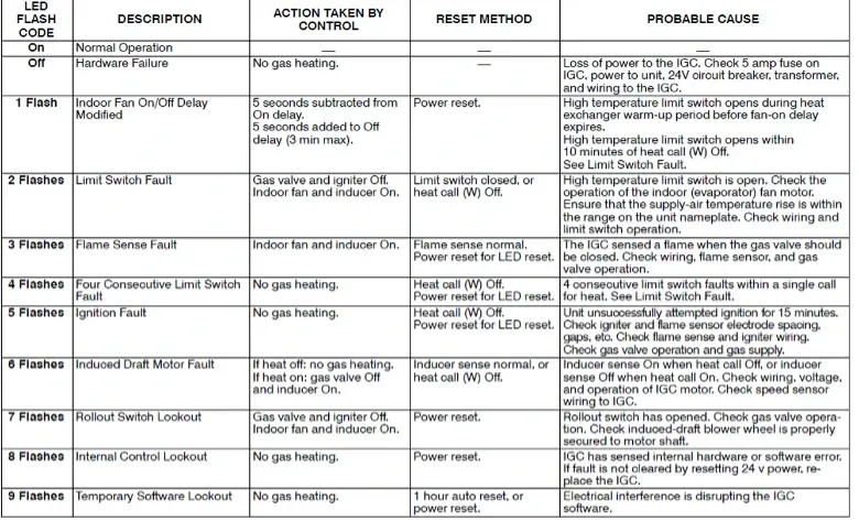
With the heating season coming up, I wanted to share a common issue and how to troubleshoot the Hall Effect switch. I’ve also included a chart with codes, what they mean, and what to look for when troubleshooting a furnace.
Troubleshooting the Hall Effect Switch
Tools needed:
Voltmeter capable of measuring DC volts
With the three-wire plug unplugged:
With power applied to the unit, unplug the three-wire plug and measure the pins as follows:
1. Connect the negative or black lead of the meter to pin three on the circuit board.
2. Connect the positive or red lead of the meter to pin one.
3. The meter should read between 7.5 and 10 volts DC.
4. Move the red or positive lead to pin two. It should read between 21 and 24 volts DC.
5. Replace the circuit board if these pins are outside these readings.
With the three-wire plug plugged in:
With power applied to the unit and the three-wire plug in place, measure the pins as follows:
1. Connect the negative or black lead of the voltmeter to pin three on the circuit board.
2. Connect the positive or red lead of the voltmeter to pin one.
3. Slowly rotate the induced draft motor. On half of one rotation of the induced draft motor shaft the voltage reading should be less than 1 volt DC. On the other half of one rotation the voltage reading should be between 6.5 and 9 volts DC.
4. If the voltage reading is not less than 1 volt DC on half of the rotation of the motor shaft and not between 6.5 volts and 9 volts DC of the other half of the shaft rotation, replace the Hall Effect Switch.
5. Move the red or positive lead to pin two. It should read between 16.5 and 21 volts. If not, replace the Hall Effect Switch.
IGC Codes

Disclaimer: The technical statements, information and recommendations contained herein are believed to be accurate as of the date hereof, but Mingledorff’s does not make representations or warranties, express or implied, as to its accuracy, its completeness, or the results to be obtained. The information is being provided for informational purposes only and is intended for use by persons having adequate skill and expertise regarding the proper selection, use and application of the products and recommendations and at their own risk and discretion.
More to Explore


