

It is a good practice to make sure all of your dip switches are set to the factory position on all of your flow selector boxes during installation. If the dip switches are not set in the factory position you will have L11 and E17 error codes to follow. You can verify the factory dip switch settings by looking at access door on the flow selector box. The L11 and E17 error codes can also be caused by wiring issues, good wiring practices can prevent having problems.


Changing dip switches on your flow selectors is not necessary because all of your flow selector addresses and port numbers are set using and codes 00FE and 0105 on your thermostat. Making sure your flow selector address and your flow selector port address is correct will make the start up process much easier. If care is taken and you have a good understanding of the wiring and installation of a VRF system the start up process can be close to seamless.


L11- Detected indoor unit address, Flow selector unit not connected.


E17- Communication trouble between indoor unit and flow selector unit.

Brett Stewart

VRF Tech Support & Equipment Verification Southwest District

January 15, 2025

Relays and Relay Capabilities (RIBU1C & RIBU2C)

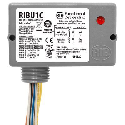
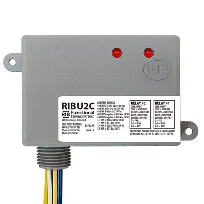
There are many capabilities and functions of RIB relays. The RIBU1C and the RIBU2C are two of the most common and user-friendly relays. Using 10-30 AC/DC voltage or 120V AC voltage, these relays can control one or two legs of power. They are commonly used to break 120V and 208/230V high-voltage power sources. These relays have normally closed (N/C) and normally open (N/O) contacts that change state when voltage is applied or removed.


Power is applied to the N/C set of contacts on the RIBU1C through the yellow and blue wires, with yellow serving as common and blue as N/C. The N/O set of contacts is controlled by the yellow and orange wires, with yellow as common and orange as N/O. If you have a RIBU2C, it contains two relays instead of one. The wire colors for the N/C and N/O sets of contacts for the first relay are the same as those of the RIBU1C, but they differ for the second relay. For relay two, the N/C set of contacts is controlled by the purple and gray wires, with purple as common and gray as N/C. The N/O set of contacts for relay two is controlled by the purple and brown wires, with purple as common and brown as N/O.


These relays are a simple solution for interlocking external pieces of equipment with various HVAC systems, such as interlocking a rooftop unit with a 120V exhaust fan. When the indoor fan on the rooftop unit is energized, the contacts on the RIB relay close, activating the exhaust fan. By utilizing C and R on the rooftop control board with the Wht/Yell and Wht/Blu wires on the RIB relay, along with the yellow and orange wires to break 120V for the exhaust fan using the N/O contacts, this process can be achieved effectively.


These relays are suitable for both commercial and residential applications. They are widely available at most major HVAC suppliers and are quick and easy to install.

Gray RIB relay control box with red indicator light and attached wires on a white background
Gray RIB U2C relay control module with red LEDs and attached wires on a white background

Disclaimer: The technical statements, information and recommendations contained herein are believed to be accurate as of the date hereof, but Mingledorff’s does not make representations or warranties, express or implied, as to its accuracy, its completeness, or the results to be obtained. The information is being provided for informational purposes only and is intended for use by persons having adequate skill and expertise regarding the proper selection, use and application of the products and recommendations and at their own risk and discretion.


More to Explore

September 16, 2026
Disclaimer: The technical statements, information and recommendations contained herein are believed to be accurate as of the date hereof, but Mingledorff’s does not make representations or warranties, express or implied, as to its accuracy, its completeness, or the results to be obtained. The information is being provided for informational purposes only and is intended for use by persons having adequate skill and expertise regarding the proper selection, use and application of the products and recommendations and at their own risk and discretion. 

By Jesse Van Atta • September 16, 2026
Disclaimer: The technical statements, information and recommendations contained herein are believed to be accurate as of the date hereof, but Mingledorff’s does not make representations or warranties, express or implied, as to its accuracy, its completeness, or the results to be obtained. The information is being provided for informational purposes only and is intended for use by persons having adequate skill and expertise regarding the proper selection, use and application of the products and recommendations and at their own risk and discretion.