It is a good practice to make sure all of your dip switches are set to the factory position on all of your flow selector boxes during installation. If the dip switches are not set in the factory position you will have L11 and E17 error codes to follow. You can verify the factory dip switch settings by looking at access door on the flow selector box. The L11 and E17 error codes can also be caused by wiring issues, good wiring practices can prevent having problems.


Changing dip switches on your flow selectors is not necessary because all of your flow selector addresses and port numbers are set using and codes 00FE and 0105 on your thermostat. Making sure your flow selector address and your flow selector port address is correct will make the start up process much easier. If care is taken and you have a good understanding of the wiring and installation of a VRF system the start up process can be close to seamless.


L11- Detected indoor unit address, Flow selector unit not connected.


E17- Communication trouble between indoor unit and flow selector unit.
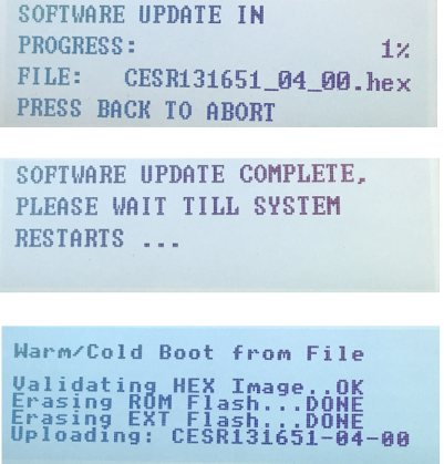
Software update screens showing firmware progress, complete message, and boot validation text on a device display

John Grenade

Technical Service Manager • Southwest District

January 12, 2024

RTU Fan Speed Setup with RTU-Open Board using Equipment Touch

You have a commercial building with multiple roof top units (48/50LC) and the Test & Balance Company is telling you they can’t adjust the air flow. The units have RTU-Open control board installed from the factory with a third-party Control Company. So, what do you do?


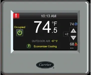
With an Equipment Touch (part# EQT1-4-CAR) and some 18-4 stranded thermostat wire you will be able to access the RTU-Open board and make changes to the airflow setting. Let’s get started.

Carrier thermostat display showing 74°F, occupied, and economizer cooling mode

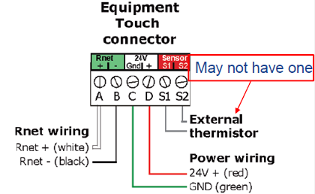
The Equipment Touch requires 24 vac for power (this can wired to R & C on the CTB located in the control section of unit) and two wires for communication to the RTU-Open board. See below:

Diagram of Touch connector wiring with Rnet, power, and optional external thermistor labels

You will wire C on the Equipment Touch connector to C on the CTB, wire D on the Equipment Touch connector to R on the CTB.


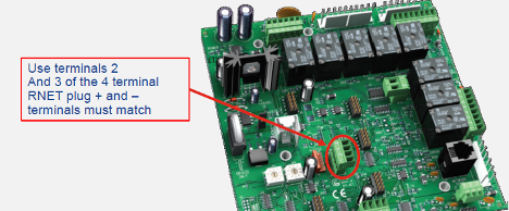
Wire A positive to terminal 2 on RTU-Open board Rnet port and B negative to terminal 3 on RTU-Open board Rnet port. See below:

Circuit board with red circle marking a 4-terminal relay and a note directing terminal use.

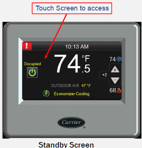
Once you have all wiring done, power up unit. The Equipment Touch will boot up and have a display. This takes a few seconds. Once this is done, the Equipment Touch will display Standby Screen, as shown below.

Carrier thermostat standby screen showing 74°F with touch screen access callout.

Just touch the Screen to access the Home Screen.


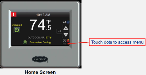
Touch the three dots in the lower right-hand corner to access the login screen. As shown below.

Thermostat home screen showing 74°F with a red arrow pointing to touch dots for the menu.

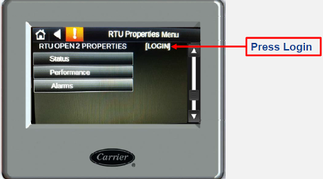
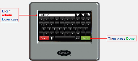
Now press LOGIN and enter admin (all lower case) as the password. Then press Done to enter the configuration menus.

Touchscreen menu with arrow labeled “Press Login” pointing to the Login option.
Diagram of a device login screen with on-screen keyboard, showing “admin” entered and “Done” button highlighted

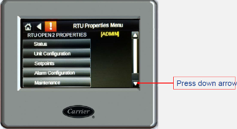
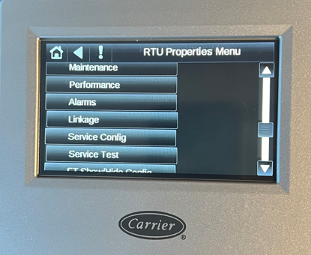
Once you have pressed done, the Equipment Touch will display this screen. You will then press the arrow down until you see Service Config tab.

Carrier thermostat screen with RTU Properties Menu and a red arrow pointing to the down arrow button
Carrier RTU properties menu on a control screen with maintenance, performance, alarms, and settings options.

Then you will touch the Service Config tab and it will display the screen below.

Carrier HVAC touchscreen showing service configuration settings and voltage values on a gray control panel.

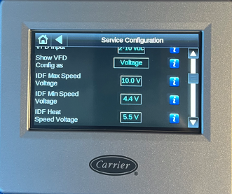
At this time, you will need to ensure that the VFD Input is set to 2-10vdc, to make a change just touch the box and highlight the correct choice. Next ensure that the Show VFD Config is set to Voltage, to make a change just touch the box and highlight the correct choice. Next touch the down arrow until you see the following on the screen

Carrier HVAC touchscreen showing service configuration settings and voltage values on a gray control panel.

There are three speed settings, Indoor Fan (IDF) Max Speed Voltage, IDF Min Speed Voltage and IDF Heat Speed Voltage. You set these settings by entering a voltage value. Higher the voltage value faster the speed of the IDF. For an example, the IDF Heat Speed Voltage is currently set at 5.5V but the Test & Balance person needs it be slowed down, you will then touch the box that has 5.5V and then the screen will let you enter a new value, if you enter 5.0 V and press done, the new entered value will be saved. The IDF will slow down.


At this time, you will decrease or increase the voltage values for all three speeds to meet airflow requirements. You will need to operate the unit in Cool Mode and Heat Mode, while in each mode you will made changes to the voltage valves as needed to meet the airflow requirements. When you are done just touch the House in the upper left-hand corner of screen to exit out. You have successfully set the up the airflow for the RTU.


Sources:


HVAC Partners-Document 11-808-652-01


Disclaimer: The technical statements, information and recommendations contained herein are believed to be accurate as of the date hereof, but Mingledorff’s does not make representations or warranties, express or implied, as to its accuracy, its completeness, or the results to be obtained. The information is being provided for informational purposes only and is intended for use by persons having adequate skill and expertise regarding the proper selection, use and application of the products and recommendations and at their own risk and discretion.


More to Explore

September 16, 2026
Disclaimer: The technical statements, information and recommendations contained herein are believed to be accurate as of the date hereof, but Mingledorff’s does not make representations or warranties, express or implied, as to its accuracy, its completeness, or the results to be obtained. The information is being provided for informational purposes only and is intended for use by persons having adequate skill and expertise regarding the proper selection, use and application of the products and recommendations and at their own risk and discretion. 
By Jesse Van Atta • September 16, 2026
Disclaimer: The technical statements, information and recommendations contained herein are believed to be accurate as of the date hereof, but Mingledorff’s does not make representations or warranties, express or implied, as to its accuracy, its completeness, or the results to be obtained. The information is being provided for informational purposes only and is intended for use by persons having adequate skill and expertise regarding the proper selection, use and application of the products and recommendations and at their own risk and discretion.