It’s important to keep HVAC Tools Calibrated
…and not just for the “by-the-book reasons Here’s why it matters in the real world: Accurate diagnostics – Gauges, thermometers, manometers,


This month we will be covering a scenario that baffled even the Mingledorff’s VRF group for a while. Hard to believe right?
Scenario: You arrive at a jobsite with a Carrier VRF unit not cooling. Looking at all the components of the system, there aren’t any errors. Maybe something is going on with the Outdoor Unit (ODU). Looking at the spot check and main boards and they both display a _0_0.
Only if it is the filter board for the #1 compressor the unit will have a blank display.
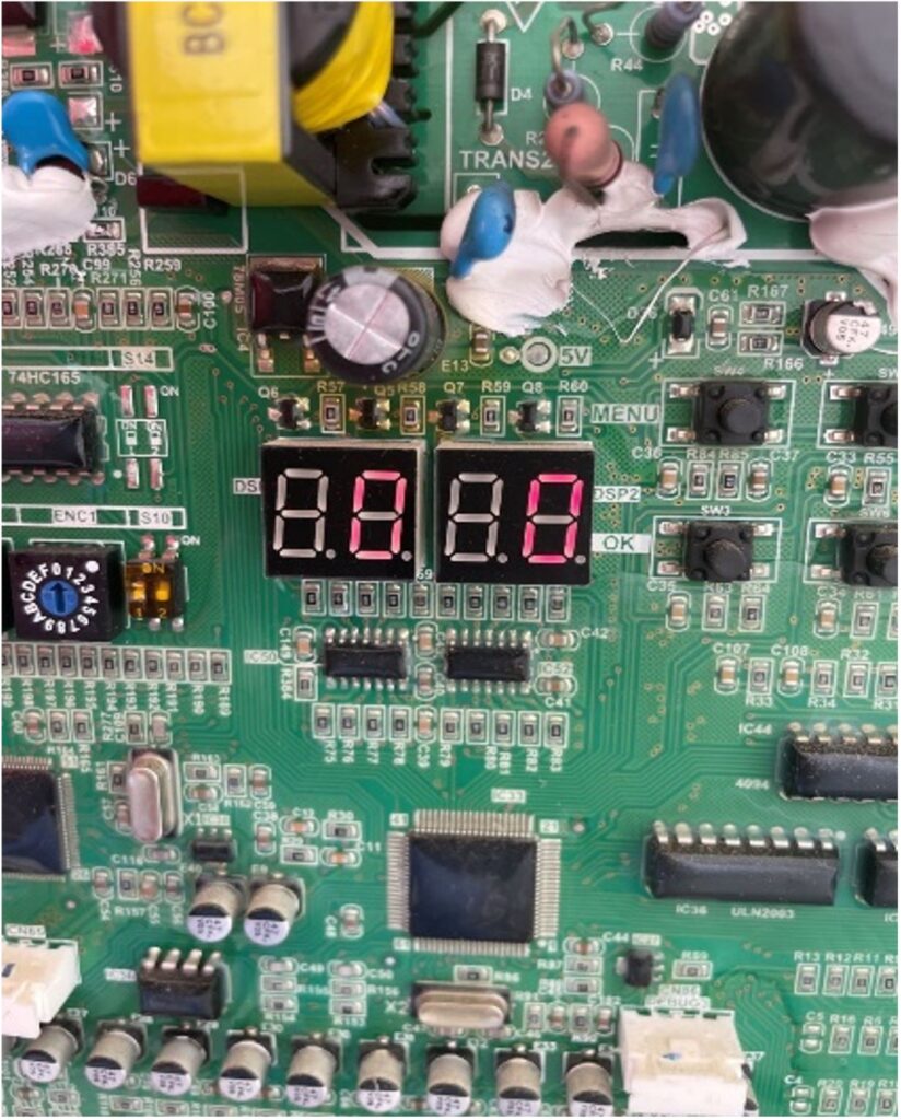
Remembering what you learned in class, this is telling you the compressors are both at 0 RPS or OFF. Time to get out the computer with STT. First thing you notice is the ODU grayed out like it’s in standby mode. “That’s weird, I know all the thermostats are set to 70 and it’s 76 degrees in the space.”

Given this very ODD scenario we need to know a little information beforehand. Every compressor and fan motor have their own inverter boards. The location of the inverter boards depends on the quantity of compressors.
Compressor 1: Left side of ODU in the main control panel behind the main board.
Compressor 2: Right side of ODU in the panel shown below.
Compressor 3: Will be the panel that is the furthest right side of the unit.

Today we will be focusing on the 2nd compressor inverter board. After removing the access panel for Compressor 2 you will see the Fuse/AC filter board. The compressor board lies behind the hinged door. LEDs can be accessed by the viewing window on the top right.

RED LED: Power to board
GREEN LED: Status/Error
If there is an error on the green LED for the Compressor 2 Inverter board use the chart below to give you an idea where to start:
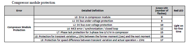
The error more than likely will be an L0 or L7 code indicating either a bad inverter board for the compressor OR fuse board.

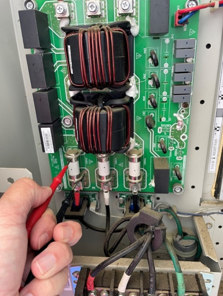
So where do we start? The easiest and fastest thing to check is the fuses. We need to ensure these non-replaceable fuses are intact. This can be accomplished 1 of 2 ways.
Power on: Check VAC voltage on either side of the fuse. If you get a voltage reading the fuse is bad. If the fuse is good, you should get a 0 VAC reading.
Power Off: Wait at least 3-5 minutes for capacitors to discharge and check continuity across the fuse.
!!WARNING!!
WHEN WORKING ON LIVE EQUIPMENT FOLLOW ALL SAFETY MEASURES. MINGLEDORFF’S IS NOT RESPONSIBLE FOR INJURY OR DAMAGE.
If any of the fuses are blown the board needs replaced. Contact your TM to order.
If you have any questions please feel free to contact the Mingledorff’s Technical Service Team.
Disclaimer: The technical statements, information and recommendations contained herein are believed to be accurate as of the date hereof, but Mingledorff’s does not make representations or warranties, express or implied, as to its accuracy, its completeness, or the results to be obtained. The information is being provided for informational purposes only and is intended for use by persons having adequate skill and expertise regarding the proper selection, use and application of the products and recommendations and at their own risk and discretion.
…and not just for the “by-the-book reasons Here’s why it matters in the real world: Accurate diagnostics – Gauges, thermometers, manometers,
This new unit is a noncommunicating variable 5 speed performance line heat pump with InteliSense technology, 19 seer2. Sizes range
When you get a new VFD drive and want to install it and you see that the other one was
We use cookies and other tracking technologies to collect and store information, operate our website, remember your preferences, deliver targeted ads and content, and enhance your experience. You can manage or change your cookie preferences at any time through your browser or device settings. To learn more, including how we collect, use, or disclose your information, please review our Privacy Policy and Terms of Use. By interacting with this cookie banner or accessing the site, you consent to our Privacy Policy and Terms of Use, including the arbitration provision and class action waiver.