Bryant only:
Bryant Service Technician
This symbol is for an equipment ground- almost any time you see three lines parallel either horizontally or vertically- they will mean earth/ ground.
Here is an Outdoor Fan Motor where you can see it contains two windings, Start and Run. Also, in green is another symbol for ground
Pulled from an indoor ceiling cassette 40MBCQ
The chart/table on outdoor units have loads more of information so I will assist in clarifying.
These units are more complex and have more variables to consider.
*to keep things simple, we typically round close decimal numbers*
Min. Piping Length per each indoor unit- This is the minimum allowed amount of lineset for each indoor unit
Standard Piping Length per each indoor unit- this is the amount of lineset that has been “reserved” for each indoor unit for refrigerant charge purposes.
Max. outdoor-indoor height difference- how far you can separate the indoor from the outdoor vertically. Two labels are shown- IU indoor unit above OU outdoor unit and vice versa.
Max. height different between indoor units- if the indoor units are on different levels, then they should not exceed this amount of vertical separation amongst themselves.
Max. Length per each indoor unit- no indoor unit should have a lineset longer than this number. Do not exceed this number for any indoor unit lineset.
Max. Piping Length with no additional refrigerant charge- add together all of the lineset lengths for all the indoor units. If your lengths are above this number, then additional charge is needed.
Total Maximum Piping Length per system– when adding together all the indoor pipe lengths, this is the total length that the unit can support. Pipe lengths greater than this are not approved nor recommended.
Additional refrigerant charge- if your total lineset length is over the “Max. Piping Length with no additional refrigerant charge” amount, this is how many ounces per foot should be added to the unit for proper operation.
Pipe sizes: these show the pipe sizes with an asterisk (*) and then the quantity of those ports.
For example: from the 36K– 1/2 *2+3/8*2
This means 2 at ½ and 2 at 3/8.
In the event that the correct line set size is ran and it is not the same size as the hookup of this unit, use the factory supplied adapters to make the connections.
February 9, 2021
Using a Standard Thermostat with a Communicating System for Emergency Operation
On rare occasions the infinity wall controllers fail. Sometimes, this failure is after hours and the supply house is closed. Periodically, homeowners do not want to purchase another wall controller due to cost and they researched their unit on the web and read that a “regular or standard” thermostat will work their Infinity system.
I have to say first, that it is highly recommended that Infinity series equipment be used with an Infinity wall control; this way all the features of the unit the customer initially bought can be utilized and when there is a malfunction it is communicated to all the equipment to better protect against further damage. The installation manual provided from Carrier for the FE4A/FE5A does NOT show an option for wiring a standard Thermostat nor Thermidistat to the fan coil, only an Infinity wall controller. Furthermore, ALL the manuals for outdoor Infinity equipment state that an Infinity wall controller MUST be used. All manuals do say however that a standard thermostat can be used to control the unit’s control boards using emergency operation modes. There is NO guarantee that it will work indefinitely because the terminals that will be used to wire the board are intended to be outputs for a non-communicating outdoor unit not inputs from a thermostat. If the unit is being ran in emergency operation with a standard thermostat then there will be no control of humidity, no air flow staging, and the unit will not provide the level of efficiency nor comfort that they were receiving with the Infinity wall controller. Carrier states in the FE4A/FE5A manual “(Emergency mode) should only be activated when User Interface cannot be replaced immediately”.
If through troubleshooting it is found that the wall controller is faulty and must be replaced, the wall controller should be changed and replaced with a newer model. If it happens to be after hours, on the weekend, a holiday, or the wall controller is not available, then the indoor and outdoor control boards will allow emergency heating and cooling operations using a standard thermostat. If the FE4A/FE5A control board does not have communication with a wall controller for a period exceeding two minutes then the unit will flash a code 16, system communication fault.
To utilize this emergency operation modes the thermostat, fan coil, and outdoor unit must be unwired from the ABCD terminals and be rewired for R, G, W, Y, O, C. When the unit is wired appropriately, the two-minute time period has lapsed, and the indoor is flashing a code 16 on the status LED the unit will start responding to the emergency inputs. If the indoor control board retains the tonnage of the outdoor equipment, then the indoor will provide the air flow of 350 CFM times the tonnage of the outdoor. If the indoor control board DOES NOT retain the information of the outdoor equipment then the indoor board will provide 350 CFM per ton for the highest possible matched outdoor unit for each indoor unit size:
002: 1050 CFM;
003/004: 1225 CFM;
005:1400 CFM;
006:1750 CFM;
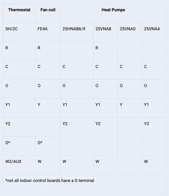
The thermostat should be programmed for either 2H/2C or 3H/2C depending on your outdoor equipment. Use the chart to wire the thermostat and follow from left to right to see where each wire will be terminated according to which model outdoor unit you have. The chart represents the latest models found in Carrier’s Catalog.

More to Explore