45 MBCA Ductless Unit and the “CP” Error Code
Most ductless products have all of the error codes listed in the installation and service manuals. Error codes listed in


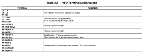
You are on a no cool service call; the unit is a 50P VAV RTU and you have diagnosis that the VFD is bad and will need to be replaced. In this article we will talk about the process of wiring and setting up the parameters for the replacement VFD.
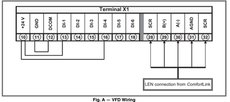
Once you receive your new VFD, it is very important to make sure it is the correct one before going to the site. When you are on site ready to install, always practice good safety measures. Turn off power and lock it out. It is a good practice to record or take a picture of all wiring on the existing VFD before removing. Once the new VFD is installed and wired up, check all wiring.
Once you have confirmed that all wiring is correct, you are now ready to restore power to the unit. When you first plug the keypad, it prompts you for Carrier Assistance. Always choose “NO”. The drives already have a program in them. If you choose “Yes”, this will make changes to the VFD program and it will add time to the setup process.
On the P Series Units, the Comfort Link sends information to the VFD’s via the Len Bus. In most applications these units will have two VFD’s, one for the Supply Fan Motor and one for the Power Exhaust Fan Motor. Each one will have a EFB Station ID number (Supply Fan is 41 & Exhaust Fan is 42).
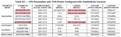
Now that you have the keypad plugged into the VFD you can start setting it up. On the keypad select Menu, use the arrows to select the Parameters menu. You will find the parameter index, verify and/or select correct chose using the Table below, once you made the selection, press save. In Table AB we will be using the “CARRIER DEFAULT” parameters setting.
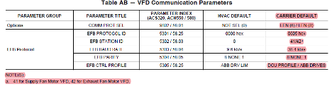
Remember when setting the EFB Station ID number make sure the correct one is chosen!!
You are almost done, just a few parameters to check. The motor information will be needed and you will get it off the motor data plate, voltage, amps, and horsepower.
Now that you have checked and made sure all the parameters are correct for your unit, there a few more steps. First, remove the keypad from the VFD and turn off power for 3 minutes. This will allow time for the components to power down. After time has elapsed, restore power to unit. Wait another 5 minutes before putting the keypad back into the VFD. This will allow time for the Comfort Link controller to boot up. Once that is done, press the AUTO button. The fan motor should start operating. Good job!
Sources:
HVAC Partners – 40-50 P-13T
Disclaimer: The technical statements, information and recommendations contained herein are believed to be accurate as of the date hereof, but Mingledorff’s does not make representations or warranties, express or implied, as to its accuracy, its completeness, or the results to be obtained. The information is being provided for informational purposes only and is intended for use by persons having adequate skill and expertise regarding the proper selection, use and application of the products and recommendations and at their own risk and discretion.
Most ductless products have all of the error codes listed in the installation and service manuals. Error codes listed in
We have multiple articles about the defrost boards for residential and commercial units on our website and each has addressed
There are several different types of ductless heating and cooling systems. These systems can be combined with various indoor and