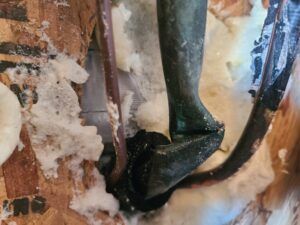
It is a good practice to make sure all of your dip switches are set to the factory position on all of your flow selector boxes during installation. If the dip switches are not set in the factory position you will have L11 and E17 error codes to follow. You can verify the factory dip switch settings by looking at access door on the flow selector box. The L11 and E17 error codes can also be caused by wiring issues, good wiring practices can prevent having problems.
Changing dip switches on your flow selectors is not necessary because all of your flow selector addresses and port numbers are set using and codes 00FE and 0105 on your thermostat. Making sure your flow selector address and your flow selector port address is correct will make the start up process much easier. If care is taken and you have a good understanding of the wiring and installation of a VRF system the start up process can be close to seamless.
L11- Detected indoor unit address, Flow selector unit not connected.
E17- Communication trouble between indoor unit and flow selector unit.
Meter leads on the DFT position 1 and the C terminal.
Schematic: The circles represent where meter leads were making contact for testing.
The Pipe Sensor:
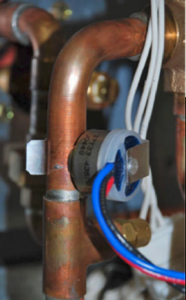
The pipe sensor monitors the temperature of the water going to a 2-pipe FCU, also known as changeover sensor, changeover switch, Aquastat, among others:
- If the water is hot (> 83 F), it signals the thermostat that the system is in heat mode;
- If the water is cold (< 65 F), it signals the thermostat that the system is in cooling mode;
- User configurable for Open or Closed activation
- Compatible with both on-Cool / on-Heat sensors (determined on 1st run setup)
- Compatible with dry-contact pipe sensors (on/off), not analog. (ex. 10K ohm thermistor)
- Dehumidify with Fan (Yes or No): when Dehum is active this setting specifies if you want the furnace/air-handler fan to run as well. This will activate (G) output on the t-stat at the same time. This can work independent of a cooling cycle.
- Min Runtime Delta (2-10%): to reduce short cycling, the dehumidifier will run beyond the desired humidity by the selected amount (%). Default is 5%.
- Dehumidify in Heat Mode (Yes or No): If humidity is a concern during the heating season and have a standalone Dehumidifier, this setting can be used to activate the Dehumidifier and will work independent of a heating cycle.
- Dehumidifier Active (Open or Closed): this setting is dependent whether the HVAC system or standalone Dehumidifier requires it to be open or closed while active. This setting is part of the 1st run setup but can change afterwards in the Dehumidifier menu.
Find the service literature for your specific outdoor unit. The compressor model numbers, and ohm values are published in every service manual for these units. Match your numbers to the chart provided on the back of the PBA and table below.
Or, if you prefer the hard way, just check the numbers on the compressor. Unfortunately, the model tags are facing the inside of the unit. You can try to get your camera phone in there and get a photo or use your mirror from your torch set and a flashlight to see back there and verify the model. Then set the SW1 dipswitches accordingly. See table below.
Once signed into your account, touch “Connect to Outdoor Unit or Furnace”. This will take you to the “Connect to Equipment” screen. Select “Outdoor Unit (Bluetooth)” and the app will search for equipment.
2. Condenser: Half the magic happens here as high-pressure vapor pumped from the compressor rejects heat until it has changed state and condensed into a high-pressure sub–cooled liquid.
If it is not present, you have a shorted PC board. If it is present, then progress to the next step. Rotate the fan by hand and measure pins 1 & 5, 2 & 5, and 3 & 5. If any negative voltage is displayed, then replace the motor.
Check The Inverter (IPM)
TXV
June 9, 2023
Why Do Systems Freeze in Cooling Mode?
When troubleshooting any issue, it is always best to start with the most probable cause and work your way to the less likely possibilities. In this article, I will cover some of the basics of why systems freeze up during cooling mode. It might seem like HVAC 101 to some, but for the new talent coming into our trade, this knowledge can be invaluable.
Low air flow and/or low refrigerant through the indoor evaporator coil
It is important to understand that refrigerant pressure and temperature are relative. If the pressure drops, then the temperature falls accordingly. If the temperature falls below freezing, then available moisture in the air will turn to frost and eventually ice. This process usually begins just past the metering device. When left unchecked, it can work its way across the coil and back to the compressor.
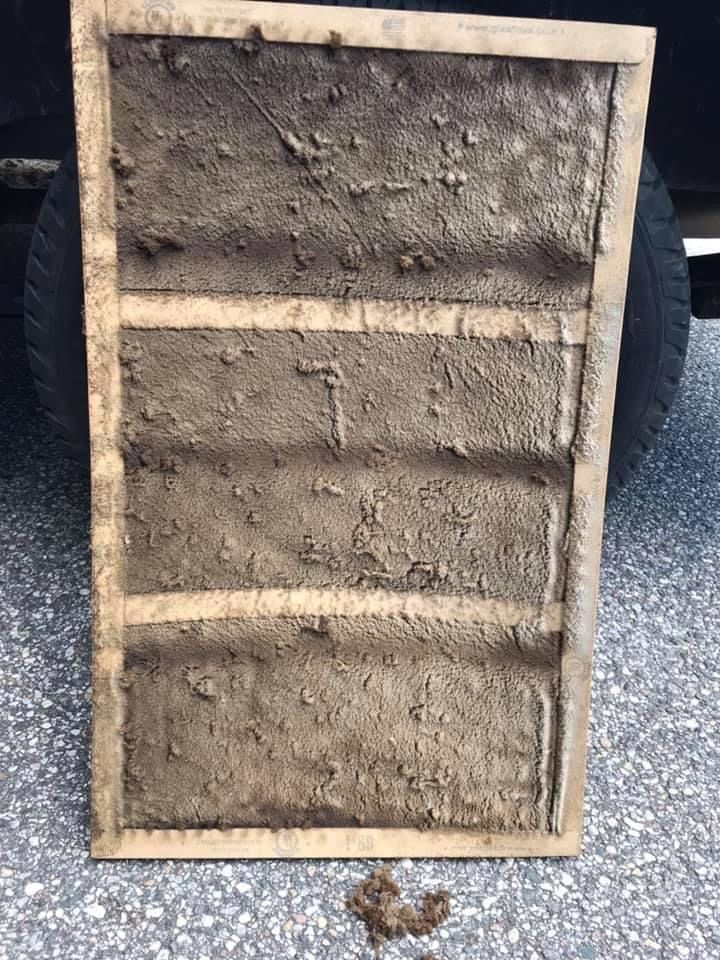
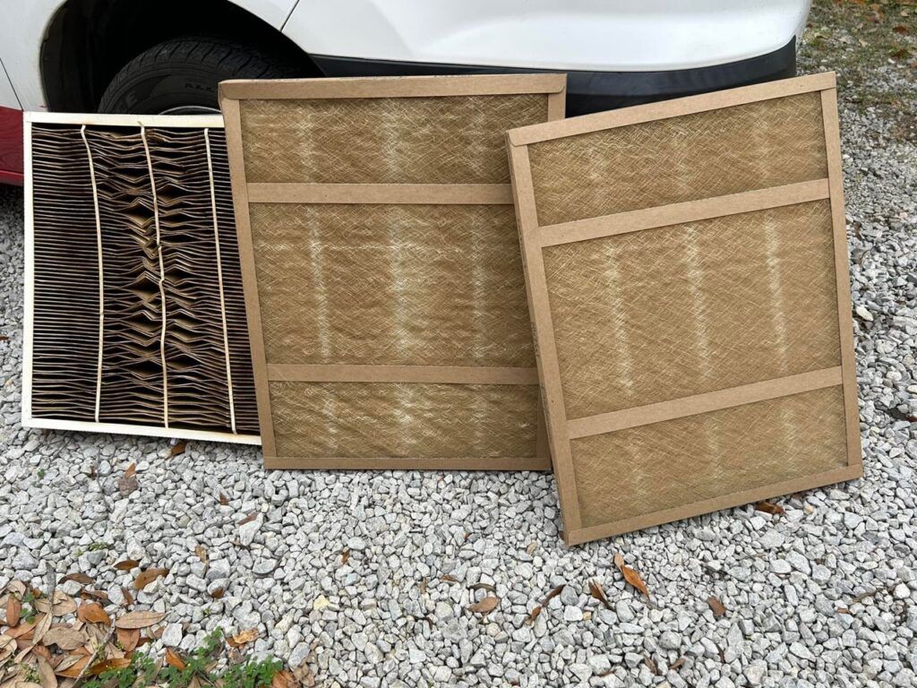
How dirty is the filter? This should always be the first thing to check.
A blower motor must draw air in to move it properly. Low airflow because of a dirty filter can reduce capacity and cause a system to freeze. Closed supply vents on a system can also cause airflow to slow down through the indoor coil. However, these may not be the only issues. Make sure to inspect the entire system thoroughly for other potential problems.


Remind Your Customers to Change Their Filters Regularly. Photos Courtesy of Josh Petty
An undersized return can contribute to a system freezing.
While checking the filter, take measurements to know if the equipment has enough return air. A good rule is 2 cfm (cubic feet per minute) of air per square inch. Your local and state codes may vary. Most conventional systems are designed to deliver 350-400 cfm per ton.
For example: A 3-ton system moving 400 cfm per ton provides 1200 cfm and requires 600 square inches of return. For this system, a 20×30 return air opening is ideal. Ductulators, sizing charts, and apps are handy tools for verifying the proper size of ductwork.
What condition is the evaporator coil?
If it is within line of sight when checking the filter, take note of accumulation or damage. If it is not visible from the filter location, put forth the effort to visually inspect the coil. Knowing the condition will assist in your final diagnosis. If it is too frozen over, you may not be able to tell until thawed.
Does the blower motor run? No… Figure out why and remedy the issue.
Is the outdoor contactor stuck closed? Yes… Replace it.
The points below are common causes for an evaporator coil freezing.
- Open blower relay
- Failed motor and ECM (Electronically Commutated Motor) module
- Loose or broken belt
- Insulation sucked into the coil or the blower
- Outdoor contactor stuck closed
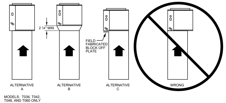
Is the cased coil installed correctly?
Many applications will have a furnace that is narrower than the evaporator coil. Always follow the guidelines set in the installation manuals. Pay attention to how air flows through the coil. Make sure all areas are getting equal distribution.

Up Flow Cased "N" Coil Installation
How does the refrigerant charge look? How is the flow?
Before you check pressures and temperatures, make sure the system is completely thawed. Any ice remaining will affect your readings.
- Low suction pressure with little to no superheat, and (usually) slightly high subcooling indicates poor airflow through the indoor coil.
- Low suction pressure with high superheat and little to no subcooling is a strong indication of low refrigerant charge.
- Low suction pressure with high superheat and high subcooling are symptoms of a refrigerant restriction.
These results may vary based on many other factors in the system.


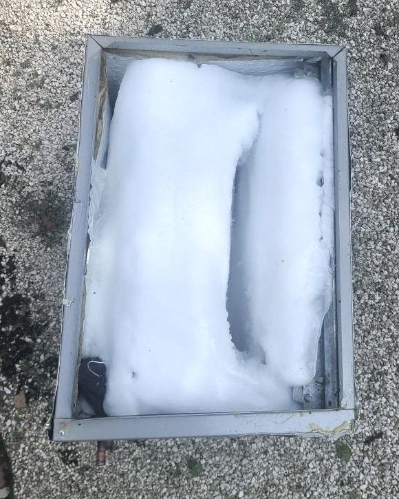
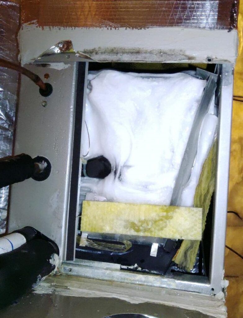
Frozen Coil from Low Refrigerant. Photos Courtesy of Joe Miller
Tech Tip: Never leak search a coil while ice is present. For many leak detectors, the change in atmosphere around thawing Ice can produce a false positive.
Is the metering device restricted?
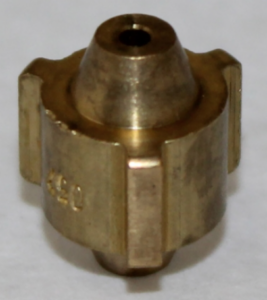
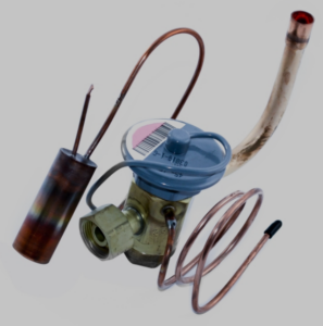
Metering devices such as pistons and TXVs are a common place for a restriction. Filter driers can occasionally become clogged. Find this issue by measuring the temperature on both sides of the drier. A temperature drop indicates a restriction. The evaporator coil itself can become restricted. Diagnose by eliminating air flow and watching for irregular freezing patterns in the capillary tubes and individual sections of the coil.

Piston

TXV

Frozen Coil from a Restricted TXV. Photo Courtesy of Daniel Gaydos

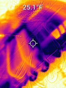
Restricted Indoor Coil Found Using a Thermal Camer
Do you have a kink in the refrigerant line?
A severe kink in a line can cause refrigerant flash and a significant drop in pressure and temperature. Sometimes, it may be necessary to read temperatures at multiple points across the lines to find this issue.

Kinked Suction Line Found in a Wall Cavity. Photo Courtesy of Joe Miller
Is there a need for low ambient cooling?
In applications such as server rooms, systems will need to run in the cool mode year-round. If the refrigerant ever falls below freezing, it begins a steady process of forming ice across the evaporator coil. In situations where low ambient cooling is required, it may be necessary to add a freeze-stat to the indoor coil and/or head pressure control at the condenser.
This article has provided a basic understanding of why systems freeze up in cooling mode. Hopefully, it has helped to elaborate on how to understand and diagnose one of the main service calls faced in the HVAC industry.

They call me Dutch… Photo courtesy of Joe Miller
Disclaimer: The technical statements, information and recommendations contained herein are believed to be accurate as of the date hereof, but Mingledorff’s does not make representations or warranties, express or implied, as to its accuracy, its completeness, or the results to be obtained. The information is being provided for informational purposes only and is intended for use by persons having adequate skill and expertise regarding the proper selection, use and application of the products and recommendations and at their own risk and discretion.
More to Explore