

October 14, 2026
CARRIER VRF: INFORMATIONAL MENUS AND LEDS
A Continuation of my "Servicing Carrier VRF" Series
There is a sea of manuals on every manufacture’s website for each piece of equipment. Buried in those manuals are usually the information that you may to help troubleshoot or verify proper operations of a system. This month I will be covering some of the menus and LEDS on the 38VM 3-Phase VRF systems (410A) and the MDC boards on Heat Recovery systems.
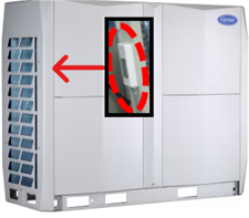
In my “Servicing Carrier VRF Part 1” we touched on where to connect on a Carrier 3 phase VRF system with a laptop. But that little board on the corner can do so much more than that. There is a query menu that allows you to quickly access information that you may not even know you had.
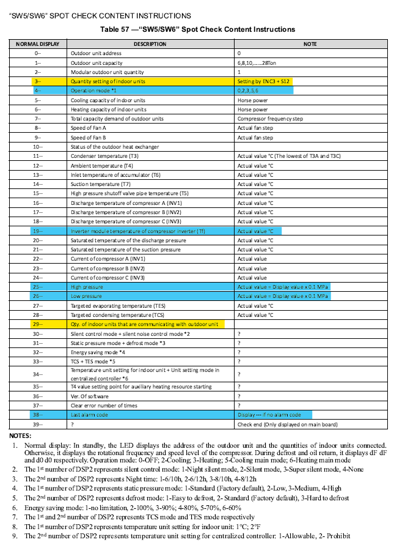
The spot check board is a mirror of the Main Board’s display. Same information but about 10+ less screws and aggravation. I’ve used this technique to help with many different troubleshooting tactics, most notably, the infamous 0H7 error. Most technicians that have worked on Carrier VRF know this code and how much they hate to see it. A little tip is within the Query menu in option 3 (Setting of ENC3 + S12) and option 29 (Qty of IDUs actively communicating with ODU). Most will know that the 0H7 is when the ENC3+S12 setting for amount of IDUs does not match the option 29 amount of active communicating IDUs.
This usually occurs when an IDU is taken down for repairs, a board is being replaced, or a janitor turns off the disconnect because someone was complaining about it being too hot/cold. Being able to match up how many IDUs are talking without connecting to it with a laptop is quick invaluable information to get you in the right direction to figuring out this annoying error.
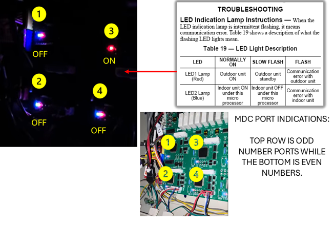
There are many other forms of instructions in the form of status LEDS. While they may not give you information as simple as the spot check, the information is still just as useful. Ever worked on a Heat Recovery unit and looked in the control area where the main boards are? I’ve been asked more times than I can count what those blue and red LEDS are telling you. I finally found the answers to all those questions and put them in a simple diagram.
This is especially useful when you have wiring for one IDU controlling another. See my article “Servicing Carrier VRF Part 3” for more details. When viewing on STT you only see the electronic address assigned to each IDU, but how do you find which copper port “address” needs to be switched in the MDC after you find out that 2 lines are crossed?
If all the IDUs are turned off and the ODU is powered, the LEDs in the MDC will reflect the status. Think of the Red LED as the ODU status and the Blue LED as the IDU status to make it easier. If you turn on just 1 IDU, the blue led changes from a flash to a solid. If there is enough capacity to bring on the ODU, the red LED will also be solid. This can be used by turning each IDU on and recording which electronic address made which set of LEDS turn from a blink to solid. The LEDs will always be in this layout: Copper port #1 is top left, the set of LEDS below it are port #2. They continue in the pattern going from left to right, top row is always odd numbered ports and bottom are even numbered ports. Knowing which IDU electronic and copper address is very useful when finding crossed ports, especially for jobs where the installing contractor didn’t leave any documentation as to what goes where.
Example: Currently IDU electronic address 6 is piped into MDC copper port 4 and electronic address 10 is piped into MDC copper port 3. You find that these 2 units are not controlling the correct IDU in heat/cool modes but found to be controlling each other. You would know that copper ports 4 and 3 in the MDC are mis-wired and just need to be swapped. Once you do this, update your documentation and know that you corrected one of the biggest issues we face when performing the QAP process during an install.
Trust me when I say that this process is much easier than the way I had to describe it. It’s not that hard but can help you solve a loss of temperature control in the space, humidity, and even get the customer to sign that maintenance contract with you.
I hope this article helped you troubleshoot that one commercial job site that has been plaquing other contractors and the end user. Be the one who documents this information and becomes the hero.
Until next month, this is JB signing off.
Disclaimer: The technical statements, information and recommendations contained herein are believed to be accurate as of the date hereof, but Mingledorff’s does not make representations or warranties, express or implied, as to its accuracy, its completeness, or the results to be obtained. The information is being provided for informational purposes only and is intended for use by persons having adequate skill and expertise regarding the proper selection, use and application of the products and recommendations and at their own risk and discretion.



