Simplified Wiring Guide for R, Y1, Y2 Terminals
Tip: click the images to open an enlarged view in another tab. Close the tab to return to the article.


Tip: click the images to open an enlarged view in another tab. Close the tab to return to the article.
On the first Tech-Tip we went over the R looper wire which went through Pins 7 and 8 on UCB Main like below as well as the LSM.
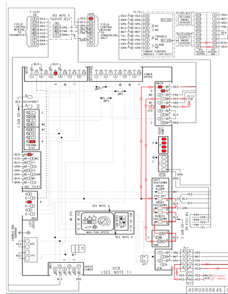
In this Tech Tip, we will go over Pins 7 and 8 again with the red looper wire as well as go over the one with the UCB going to a (VFD) Variable Frequency Drive.
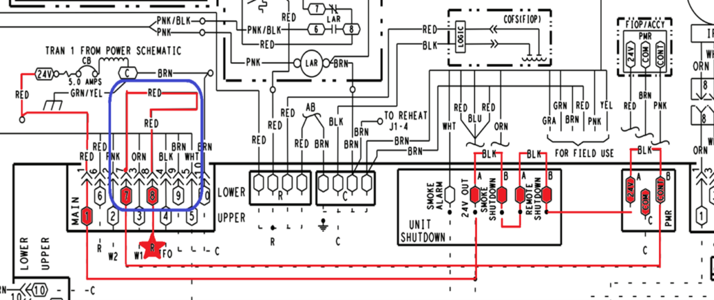
Note: The yellow letters are between Pin 7 and 8 on UCB Main!
Note: Check all voltages to ground.
Example: 24VAC Transformer Secondary to ground. Then UCB Main at Pin1 to ground then
Smoke Shutdown A to ground etc, etc…
If you have voltages all the way to Pin8 on UCB Main then you will have Voltage on R terminal.
NOTE: Everything with yellow letters is between Pin 7 and 8 on UCB Main in this example
ACS320 Drive, which has orange boxes around it in the photo below.
The ACH180 is the yellow boxes which will use Terminal 6 that will be the drive that we use for this example.
The ACH550 and the ACH580 will be the blue boxes which will use Terminal 25. I just want to make sure you see how they have written the numbers.
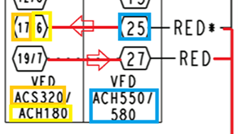
On the picture above you have VFD Drive Terminals.
RO1 Relay Output 1 Source which is either
(NO) = Normally Open which is Power off or
(NC) = Normally Closed which is Power on.
All of this is inside the VFD drive. Now we will leave the VFD drive and head back to the UCB Main Plug to complete our circuit.
Now check voltages from these pins to ground.
Disclaimer: The technical statements, information and recommendations contained herein are believed to be accurate as of the date hereof, but Mingledorff’s does not make representations or warranties, express or implied, as to its accuracy, its completeness, or the results to be obtained. The information is being provided for informational purposes only and is intended for use by persons having adequate skill and expertise regarding the proper selection, use and application of the products and recommendations and at their own risk and discretion.
Tip: click the images to open an enlarged view in another tab. Close the tab to return to the article.
HVAC technicians often work in attics, rooftops, mechanical rooms, and outdoor environments where temperatures can become dangerously high. Proper hydration
Have you ever installed or started up a commercial heat pump? Did you notice there is not an “O” terminal
We use cookies and other tracking technologies to collect and store information, operate our website, remember your preferences, deliver targeted ads and content, and enhance your experience. You can manage or change your cookie preferences at any time through your browser or device settings. To learn more, including how we collect, use, or disclose your information, please review our Privacy Policy and Terms of Use. By interacting with this cookie banner or accessing the site, you consent to our Privacy Policy and Terms of Use, including the arbitration provision and class action waiver.
You are leaving our site and we cannot be held responsible for the content of external websites.