Simplified Wiring Guide for R, Y1, Y2 Terminals
Tip: click the images to open an enlarged view in another tab. Close the tab to return to the article.


Have you ever wondered what the LED’s are used for? In this article we will discuss each one and what the difference colors represent. There are three LEDs located on the face of the controller just below the display screen. From left to right you will see a Snowflake, a Temperature Sensor, and a Damper Actuator symbol.
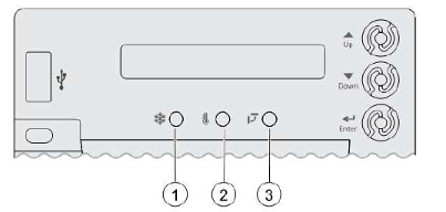
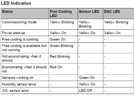
Number 1 LED is for Free Cooling, Number 2 is for the Sensors and Number 3 is for the Damper Actuator.
In the charts below you will see the status of each LED and what they represent.
Now we will discuss some of the common systoms that you will see and the possible causes and solutions.
Symptom- Brownout Protection Mode. If the voltage is below 17 VAC, the Economizer Controller will go into this mode. This mode diables all of the relay outputs. When the power is 19 VAC or higher, the Economizer Controller will operate normally.
Symptom- An alarm is dispalyed on the LCD screen. Possible issue is sensor, damper, or the whole working system may not work properly. Check sensor, damper, or the whole system following the detailed alarm imformation per the manual.
Symptom- DAC LED is blinking RED. Possible issue is Damper slippage. Check whether the damper works properly.
Symptom- DAC LED is blinking RED very fast. Possible issue is that the damper is unplugged. Check whether the damper is connected.
Symptom- DAC LED is OFF. Issue is that there is no feedback signal to the controller. Check whether the feedback signal is connected.
Symptom- Sensor LED is solid RED. Possible issue is Mixed Air Sensor or Outside Air or Return Air Sensor configuration, must be either Type II NTC 10K or 0-10 vdc sensor.
Symptom- Sensor LED is YELLOW. Possible issue sensor connection, sensor type and signal.
Symptom- Sensor LED is OFF. Possible issue is CO2 sensor connection, sensor type and sensor signal type.
NOTICE:
If different fault events occur at the same time, Sensor/DAC LED lights up following the priority below:
RED (Fast Blinking) – RED (on, Steady) – RED (Blinking) -YELLOW-Off- Green. For example, if there is a humidity sensor error and air temperature failure at the same time, the Sensor LED turns red rather than yellow.
Also, after the controller enters the running state mode, it may take one minute for the peripheral devices to complete initialization. Before that, LED indication might be unstable.
Sources:
HAVC Partners, POL224.00 APP Guide, IIK-CRECON-SRT-01
Disclaimer: The technical statements, information and recommendations contained herein are believed to be accurate as of the date hereof, but Mingledorff’s does not make representations or warranties, express or implied, as to its accuracy, its completeness, or the results to be obtained. The information is being provided for informational purposes only and is intended for use by persons having adequate skill and expertise regarding the proper selection, use and application of the products and recommendations and at their own risk and discretion.
Tip: click the images to open an enlarged view in another tab. Close the tab to return to the article.
HVAC technicians often work in attics, rooftops, mechanical rooms, and outdoor environments where temperatures can become dangerously high. Proper hydration
Have you ever installed or started up a commercial heat pump? Did you notice there is not an “O” terminal
We use cookies and other tracking technologies to collect and store information, operate our website, remember your preferences, deliver targeted ads and content, and enhance your experience. You can manage or change your cookie preferences at any time through your browser or device settings. To learn more, including how we collect, use, or disclose your information, please review our Privacy Policy and Terms of Use. By interacting with this cookie banner or accessing the site, you consent to our Privacy Policy and Terms of Use, including the arbitration provision and class action waiver.
You are leaving our site and we cannot be held responsible for the content of external websites.