Other ways to check your defrost thermostat when you don’t have ice around it, is to run the heat pump on heat mode and carefully remove the black wire from the relay on top of the defrost board. This will stop the fan from running and the condenser coil should start frosting, making the temperature of the defrost thermostat 32° ± 3°F and checking the resistance until it closes reading 0.0 ohms indicating that is working properly. If not, it may be stuck open. Replace the thermostat. You can also remove the defrost thermostat from the heat pump and insert it into a cup with ice and water. Make sure the water its 32° ± 3°F, that way you know if it closes, the defrost works. If not, replace.


The other problem could be it’s stuck closed. You always need to know the temperature that surrounds the defrost thermostat. If it is attached to a pipe, you need to know the temperature of that pipe. Otherwise, you will be guessing. In the photo below, we have a temperature above 65° ± 5°F. We know the defrost thermostat should be open and on this defrost sensor it is open.

Sergio Nieto

Technical Services Manager North Georgia

May 14, 2025

Condensation From a High Efficiency Furnace

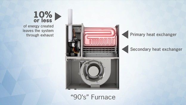
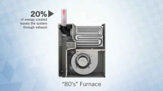
High efficiency furnaces, also known as 90% furnaces or condensing furnaces, use two heat exchangers to remove more heat from the combustion process than their mid-efficiency counterparts, which are known as 80% furnaces and only have one heat exchanger.

High-Efficiency 90% furnace vs. Mid-Efficiency 80% furnace:

Cutaway of a 90s furnace showing primary and secondary heat exchangers and exhaust heat loss.
80% of energy from an 80s furnace leaves the system through exhaust, with 20% used as heat.

Because of this, they generate flue gases much colder than those of a mid-efficiency 80% furnace. This doesn’t only change the way the furnace operates. It also changes the installation process as well.


In a high efficiency furnace, a great amount of condensation is involved. This water comes from two sources: the moisture that is already present in the air, and the combustion process itself, as the hydrogen atoms from the natural or propane gas molecules combine with oxygen to form water.


For the furnace to work properly, that condensation needs to be drained out or else it will accumulate inside the heat exchanger or inducer assembly. Most furnaces will have at least 2 internal drains, typically one for the heat exchanger and one for the vent, usually at the inducer outlet or on the inducer housing.


The secondary heat exchanger outlet is sealed inside a plastic part called the collector box, which is designed to collect the condensate and drain it out. All condensate drains go into a trap. The condensate trap is mandatory for a high efficiency gas furnace since the drain connects to the exhaust system of the furnace, leaving it open to the air. This would allow for a potential exhaust/flue gas leak in the living space and that’s why we need a condensate trap. Additionally, if there is no trap, the inducer motor would take air through the drain if it was left open, which could affect combustion and would prevent proper drainage.


One thing to think about when dealing with a condensate trap is potential blockage. The trap needs to be cleaned out regularly, and that should be done every maintenance. Rinse it out and make sure water flows through the trap properly from all its ports. If there is poor flow fill it up and blow through it to get out any obstructions.


The need for regular cleaning also means that drains should be installed in a way that allows the trap to be easily removed. Most furnaces come with additional parts like clamps and flexible hoses for installation. This makes it a little more accessible for the technician.


To ensure proper drainage, here are some helpful tips: make sure every component that produces condensate is sloped towards the drain. That means slope the vent down towards the furnace (typically a ¼’’ slope per foot of length, minimum) and slope the furnace itself! Look in your installation manual, most manufacturers will call for the furnace to be installed with a slight forward pitch to allow condensate to drain from the collector box. Slope the drain line and vent the drain after the trap to prevent airlock.


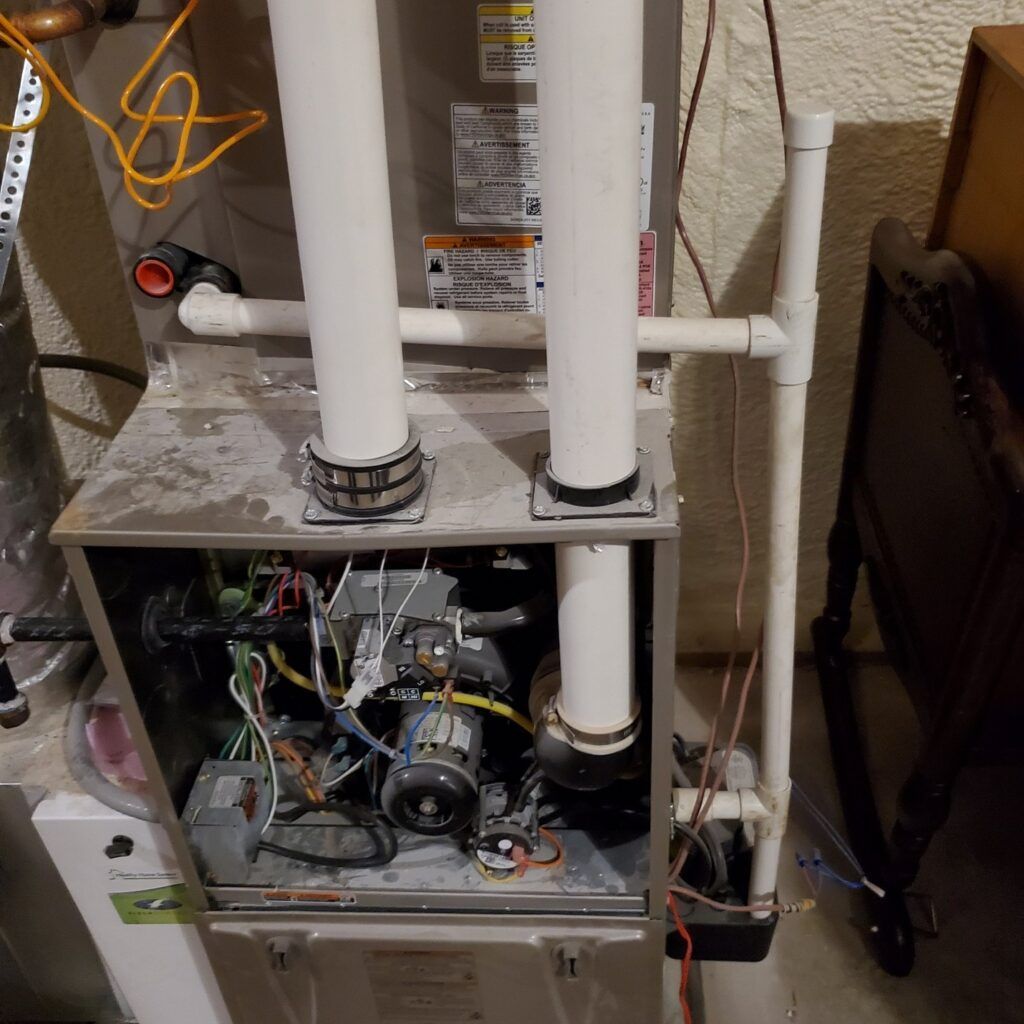
Open furnace cabinet with exposed wiring, pipes, and blower components in a utility room
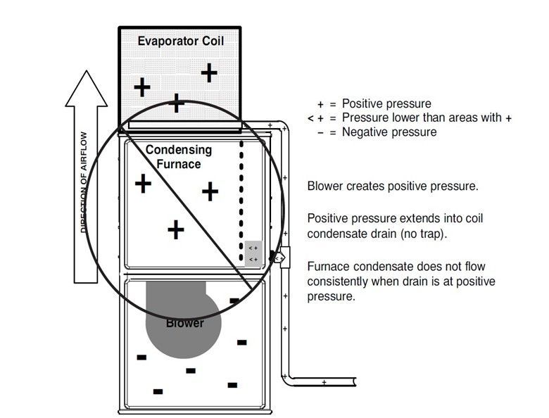
Diagram of furnace airflow and pressure zones around evaporator and condensing coils, with arrows and labels.

The photo on the left shows the wrong installation of the drain line from the condensate trap coming out of the furnace into the T from the evaporator PVC Pipe down to the condensate pump. There is no airgap inside the pump and that is not how the installation instructions are telling us to run the drain lines. The drawing on the right shows why it is not allowed.


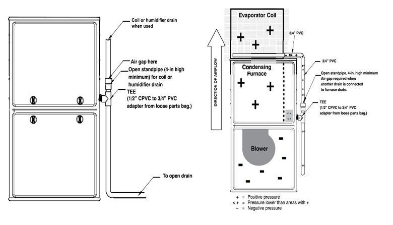
Following the instructions on the manual for a 987MC High Efficiency furnace, two of the proper ways we can run or install the drains for a furnace like the photo above is to follow the drawings below.

Annotated front and side view of a rechargeable battery compartment with labeled parts and dimensions

If you have any doubt that the installation or servicing methods that you are using are correct you should always refer to your installation manual, product data, submittals and your local codes.


All equipment is shipped with an installation guide specific to that equipment. Something to keep in mind is that different manufacturers may call for different installation procedures! Just another reason to ALWAYS follow the installation instructions.


Disclaimer: The technical statements, information and recommendations contained herein are believed to be accurate as of the date hereof, but Mingledorff’s does not make representations or warranties, express or implied, as to its accuracy, its completeness, or the results to be obtained. The information is being provided for informational purposes only and is intended for use by persons having adequate skill and expertise regarding the proper selection, use and application of the products and recommendations and at their own risk and discretion.


More to Explore

September 16, 2026
Disclaimer: The technical statements, information and recommendations contained herein are believed to be accurate as of the date hereof, but Mingledorff’s does not make representations or warranties, express or implied, as to its accuracy, its completeness, or the results to be obtained. The information is being provided for informational purposes only and is intended for use by persons having adequate skill and expertise regarding the proper selection, use and application of the products and recommendations and at their own risk and discretion. 
By Jesse Van Atta September 16, 2026
Disclaimer: The technical statements, information and recommendations contained herein are believed to be accurate as of the date hereof, but Mingledorff’s does not make representations or warranties, express or implied, as to its accuracy, its completeness, or the results to be obtained. The information is being provided for informational purposes only and is intended for use by persons having adequate skill and expertise regarding the proper selection, use and application of the products and recommendations and at their own risk and discretion.