

It is a good practice to make sure all of your dip switches are set to the factory position on all of your flow selector boxes during installation. If the dip switches are not set in the factory position you will have L11 and E17 error codes to follow. You can verify the factory dip switch settings by looking at access door on the flow selector box. The L11 and E17 error codes can also be caused by wiring issues, good wiring practices can prevent having problems.


Changing dip switches on your flow selectors is not necessary because all of your flow selector addresses and port numbers are set using and codes 00FE and 0105 on your thermostat. Making sure your flow selector address and your flow selector port address is correct will make the start up process much easier. If care is taken and you have a good understanding of the wiring and installation of a VRF system the start up process can be close to seamless.


L11- Detected indoor unit address, Flow selector unit not connected.


E17- Communication trouble between indoor unit and flow selector unit.

Shawn Pettersen

Technical Service Manager • North Georgia

March 18, 2024

Defrost Board Troubleshooting

I want to go over the process of troubleshooting a heat pump defrost board. This includes checking for common issues. Start by examining the board for visible damage or burnt components. Now we need to use a multimeter to test continuity, voltage, and resistance at various points on the board.


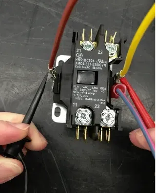
The first place we need to check is to see if we are getting power to the board. Here we are checking for the 24 volts at the contactor.

Hand holding a black relay with red, yellow, and blue wires connected on a workbench

1. Now we check the board for 24 volts. The T1 terminal on the defrost board powers the defrost timing function. This terminal must be energized before any defrost function will occur.


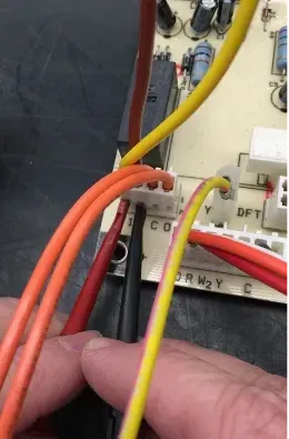
2. If the unit does not go into defrost after performing the speed up, check for 24 volts on the T1 terminal. This terminal powers the defrost circuit, and must be energized before any defrost function can occur. The T1 should be energized once the Y terminal is energized and the pressure switches are closed. Ensure the T1 wire is connected at the contactor, and that 24 volts is present on the T1 spade terminal.

Close-up of hands plugging orange and yellow wires into a small electrical terminal block.

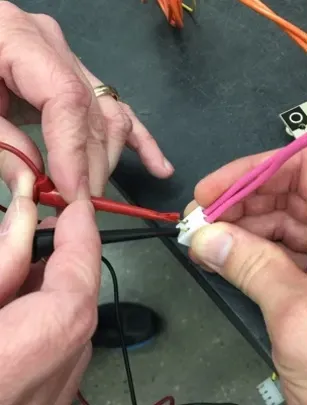
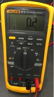
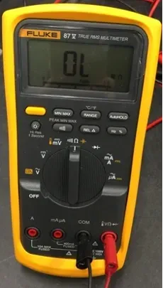
Check to see if the defrost switch is open or closed. Disconnect defrost thermostat leads from control board, and connect to ohmmeter. Thermostat leads are pink, insulated wires connected to DFT and R terminals on control board. Resistance reading may be zero (indicating closed defrost thermostat), or infinity (OL for open thermostat) depending on outdoor temperature.

Hands wiring red and pink cables into a small white connector on a workbench
Yellow Fluke digital multimeter showing 0.2 on the display, with red and black probes plugged in.
Fluke digital multimeter showing “OL,” with red and black probes plugged in at the bottom.

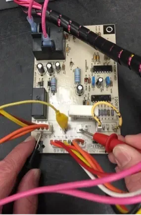
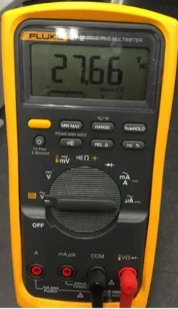
Now we want to check for 24 volts on the DFT terminal. Checking that the defrost board is supplying power to the defrost Switch.

Close-up of hands probing a circuit board with red and yellow test leads and wires.
Yellow digital multimeter displaying 27.66, with black dial and red probe plugged in on the right

Meter leads on the DFT position 1 and the C terminal.


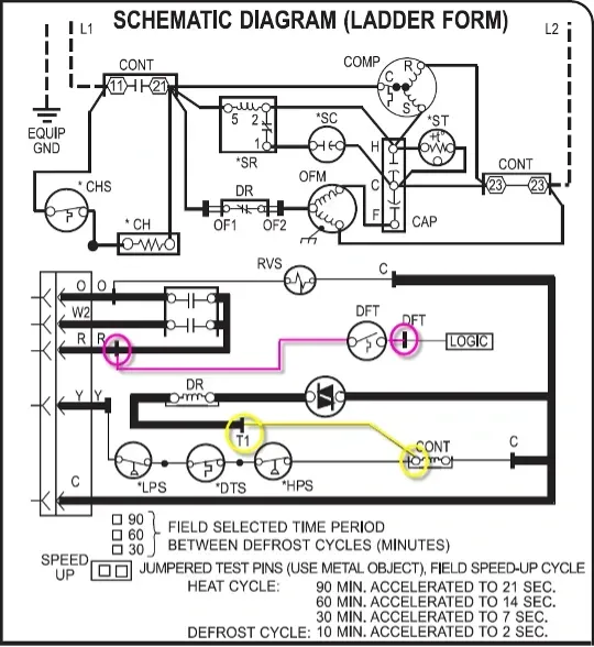
Schematic: The circles represent where meter leads were making contact for testing.

Black-and-white ladder-form schematic diagram with colored highlighted paths in magenta and yellow.

Disclaimer: The technical statements, information and recommendations contained herein are believed to be accurate as of the date hereof, but Mingledorff’s does not make representations or warranties, express or implied, as to its accuracy, its completeness, or the results to be obtained. The information is being provided for informational purposes only and is intended for use by persons having adequate skill and expertise regarding the proper selection, use and application of the products and recommendations and at their own risk and discretion.


More to Explore

September 16, 2026
Disclaimer: The technical statements, information and recommendations contained herein are believed to be accurate as of the date hereof, but Mingledorff’s does not make representations or warranties, express or implied, as to its accuracy, its completeness, or the results to be obtained. The information is being provided for informational purposes only and is intended for use by persons having adequate skill and expertise regarding the proper selection, use and application of the products and recommendations and at their own risk and discretion. 

By Jesse Van Atta • September 16, 2026
Disclaimer: The technical statements, information and recommendations contained herein are believed to be accurate as of the date hereof, but Mingledorff’s does not make representations or warranties, express or implied, as to its accuracy, its completeness, or the results to be obtained. The information is being provided for informational purposes only and is intended for use by persons having adequate skill and expertise regarding the proper selection, use and application of the products and recommendations and at their own risk and discretion.