Taking NATE Online
We have recently begun teaching our NATE classes online using zoom format. This article will hopefully clear up some of


Tip: click the images to open an enlarged view in another tab. Close the tab to return to the article.
On the first Tech-Tip we went over the R looper wire which went through Pins 7 and 8 on UCB Main like below as well as the LSM.
In the second Tech Tip of this series, we went over examples of the UCB going to a (VFD) Variable Frequency Drive.
In this one, we will discuss Commercial Air Handlers / 40RL R454B 07-12 Dissipation and EcoBlue.
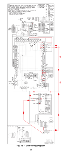
IDBC 24vac from transformer goes to UCB Main Pin 1
Smoke Shutdown A
Smoke Shutdown B
Remote Shutdown A
Remote Shutdown B
Phase Monitor (PMR) A(24v)
Phase Monitor (PMR) B(CONT)
Main Pin 7
PL12 Pin 1
PL1 Pin 8
PL1 Pin 11
PL12 Pin 2
RDB J1 Pin 5 Through R4 to
RDB J1 Pin 4
Main Pin 8
R
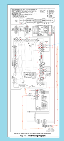
IDBC 24vac from transformer
UCB Main Pin 1
UCB Smoke Shutdown A
UCB Smoke Shutdown B
UCB Remote Shutdown A
UCB Remote Shutdown B
UCB Phase Monitor (PMR) A(24v)
UCB Phase Monitor (PMR) B(CONT)
UCB Main Pin 7
PL12 Pin 1
PL1 Pin 8
VFD Drive ACH180 use 6/ACH580 use 25. RO1 Relay Output 1 Source (NO Power off)( NC Power on)
VFD Drive ACH180 use 7/ACH580 use 27. RO1 Relay Output 1 Source
PL1 Pin 11
PL12 Pin 2
RDB J1 Pin 5 Through R4 to
RDB J1 Pin 4
UCB Main Pin 8
R
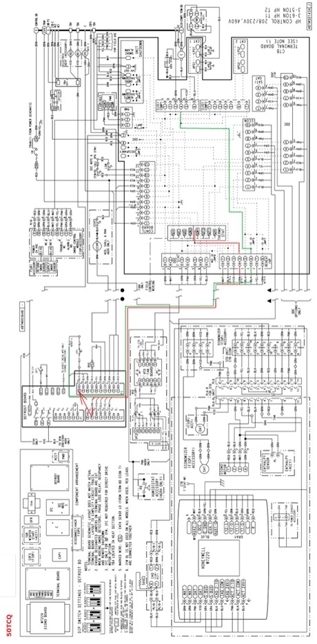
Now to look at a CTB board same concept but different pins.
Note: the dark lines represent boards and controls. Notice the dark line around the IGC board as well as the dark lines around the CTB or Control Terminal Board.
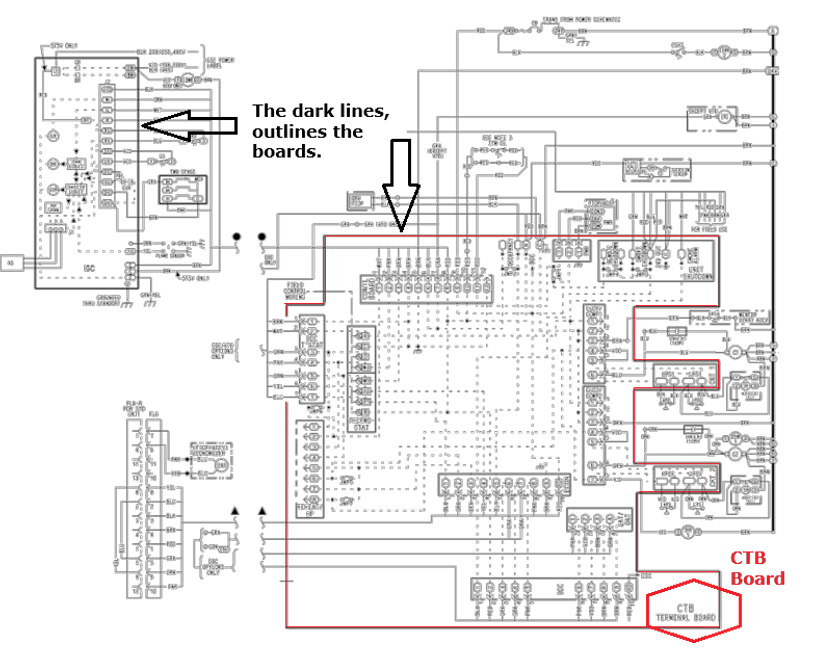
On the picture above:
R Safety Circuit for CTB. CTB uses (Pin10 – Pin11)
Transformer
CTB Contl Board Pin9
CTB Smoke Shutdown A
CTB Smoke Shutdown B
CTB Remote Shutdown A
CTB Remote Shutdown B
CTB Phase Monitor A (24v)
CTB Phase Monitor B (Cont)
CTB Contl Board Pin11
CTB IFM OL A
CTB IFM OL B
CTB Contl Board Pin10
CTB R
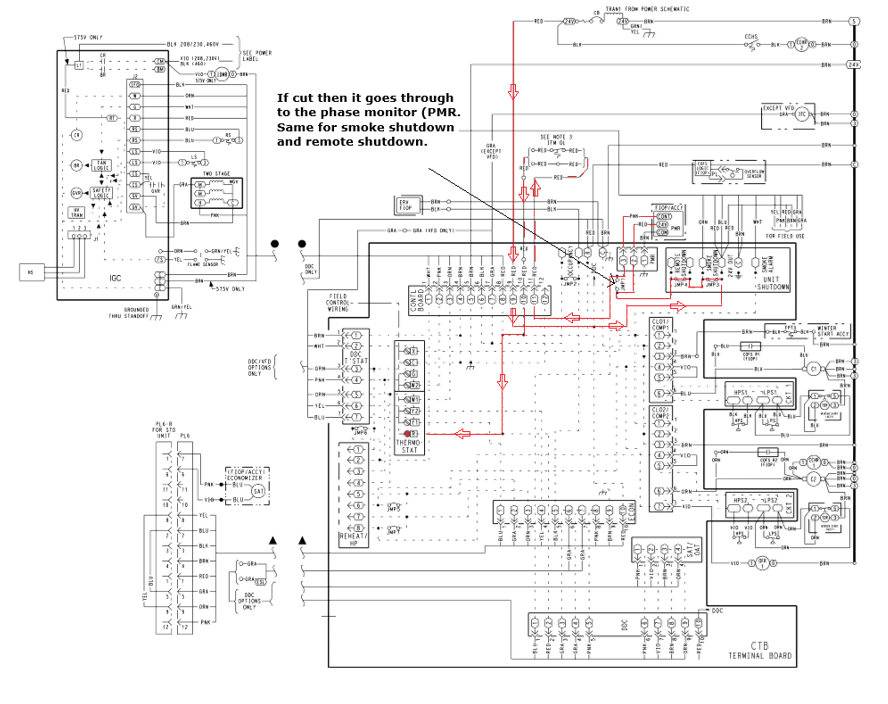
24vac from Transformer to ground
Note: Jumper should be on R and W1
CTB W1
CTB Reheat/HP Pin4
Defrost Board P2 Pin7
P3 Pin10
FPT Entering
FPT Leaving
CTB Reheat/HP Pin6
CTB CLO1/COMP1 Pin4
CTB CLO1/COMP1 Pin5
CTB LPS1 Entering
CTB LPS1 Leaving
CTB HPS2 Entering
CTB HPS2 Leaving
CTB CLO1/COMP1 Pin6
Contactor 24vac side.
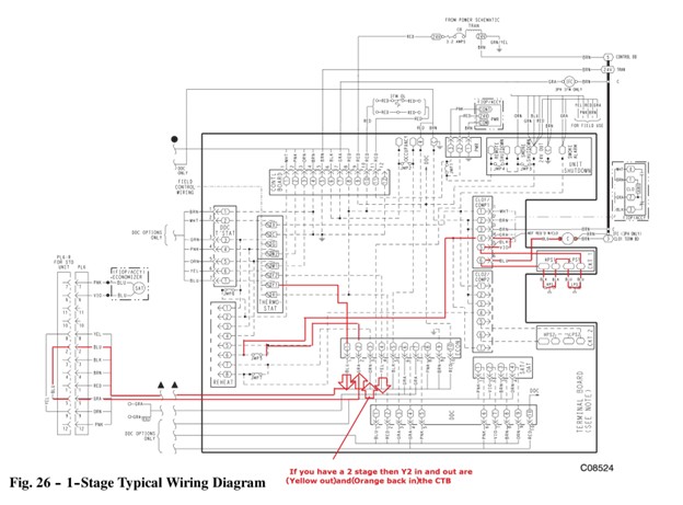
COMMERCIAL IGC BOARD (Y1 CIRCUIT WALKTHROUGH)
CTB Y1
Note: Jumper should be on R and Y1
CTB Y1
CTB Econ Pin1
CTB PL6 Pin2
CTB Pl6R Pin2
CTB Pl6R Pin5
CTB Pl6 Pin 5
CTB Econ Pin2
CTB Reheat Pin6
CTB CLO1/COMP1 Pin4
CTB CLO1/COMP1 Pin5
CTB LPS1 Entering
CTB LPS! Leaving
CTB LPS2 Entering
CTB LPS2 Leaving
CTB CLO1/COMP1 Pin6
Contactor 24vac side.
Disclaimer: The technical statements, information and recommendations contained herein are believed to be accurate as of the date hereof, but Mingledorff’s does not make representations or warranties, express or implied, as to its accuracy, its completeness, or the results to be obtained. The information is being provided for informational purposes only and is intended for use by persons having adequate skill and expertise regarding the proper selection, use and application of the products and recommendations and at their own risk and discretion.
We have recently begun teaching our NATE classes online using zoom format. This article will hopefully clear up some of
Coming back to work after an extended weekend of 4th of July there’s paperwork handed to you for the emergency
Carrier has approved the use of Crossover equipment with zoning applications. The instructions for this will be released in several phases during 2026. Release dates for
We use cookies and other tracking technologies to collect and store information, operate our website, remember your preferences, deliver targeted ads and content, and enhance your experience. You can manage or change your cookie preferences at any time through your browser or device settings. To learn more, including how we collect, use, or disclose your information, please review our Privacy Policy and Terms of Use. By interacting with this cookie banner or accessing the site, you consent to our Privacy Policy and Terms of Use, including the arbitration provision and class action waiver.
You are leaving our site and we cannot be held responsible for the content of external websites.