Brazing
Brazing is the process of joining two metals together without the wick effect that solder has.
It consists of two similar metals or dissimilar metals being joined by a brazing rod that melts before the metal being joined will. This will help assist in the bonding process. You can butt the two pieces together and braze them and it will be stronger than a soldered joint. The copper pipes can get red and silver solder will already be melted at this point.
Now a few other terms we must be aware of:
Liquidous temperature is the lowest temperature at which a metal is liquid. Solidus temperature is the highest temperature at which the metal is completely solid.
The temperature at which metal melts is called its melting point.
Brazing uses a higher temperature to melt the rods than soldering. Gas torches such as MAPP gas or oxy acetylene could be used depending on the environment and the size of pipe. MAPP gas works well in non-windy areas for up to ¾ inch pipe. Anything larger than that would push the limits of the heat.
In brazing, the components that make up the rods is determined by the metals you want to join. For the HVACR industry, we typically use silver solder containing different percentages of silver. This will determine the fluidity of the rod on the metal being joined, the cleanliness of the joint for aesthetics, and the strength of the joint.
Flux can come in various forms such as a paste or a coating on the rods. In the example for the HVACR purposes we will use 15% silver solder. An example composition of 15% Silver Solder is: 15% Silver, 80% Copper, 5% Phosphorous. In joining copper to copper, none of these phosphorus/silver/copper rods need flux or would even benefit from it. The phosphorus allows the rod to self-flux on copper. So, if you use the silver solder it has phosphorus in it and does not need flux. It is the flux!
Example: Two pipes cleaned and placed inside a coupling. Heat the pipes until the 15 percent silver solder melts and spreads smoothly along the metal joint between the pipe and the coupling. Then do the other pipe at the joint at the coupling as well. Then stop and allow to cool. Or use a wet rag to cool it down.
Round 2 terminal capacitor
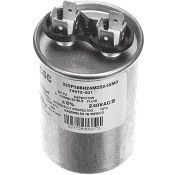
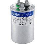
Round 3 Terminal Dual Capacitor
Oval Capacitor
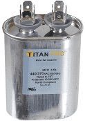
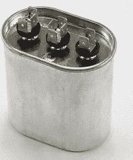
Oval Dual Capacitor
Start Capacitor - Black
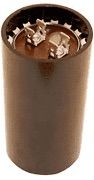
Start Capacitor - Brown