Disclaimer: The technical statements, information and recommendations contained herein are believed to be accurate as of the date hereof, but Mingledorff’s does not make representations or warranties, express or implied, as to its accuracy, its completeness, or the results to be obtained. The information is being provided for informational purposes only and is intended for use by persons having adequate skill and expertise regarding the proper selection, use and application of the products and recommendations and at their own risk and discretion.
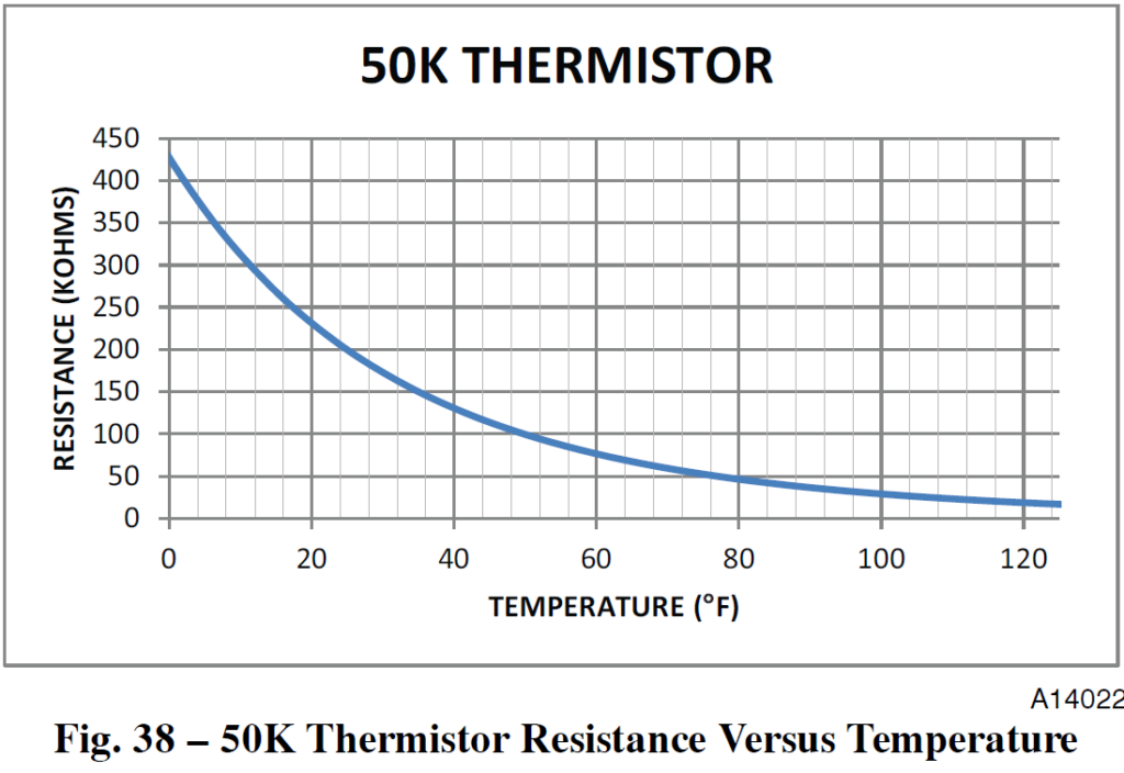

50K thermistor resistance-vs-temperature graph, blue curve on gray grid, resistance drops as temperature rises

Bubba Moore

Technical Services Manager Southeast District

February 10, 2022

Troubleshooting Electrical Problems: Voltage and Current

Troubleshooting electrical problems in an HVAC system can feel complicated. Sometimes the problem is overlooked as a faulty part. How often do we look beyond the obvious after the motors or compressors fail electrically?


Let’s first look at the incoming voltage. If the voltage is too high or too low, it can cause the motor to fail due to overheating. The voltage should fall between a minimum and a maximum limit that is listed on the data plate of the components. The voltage that is going to a motor or compressor should be within plus or minus 10% of the voltage listed on the data plate. For example, a 208/230-volt motor voltage range would be between 187 volts (208 – 10%) and 253 volts (230 +10%). On 3-phase units, voltages between phases must be balanced within 2%, or we have what is called phase imbalance. For example, if there was a 5% imbalance on the three- phase voltage, it could cause the motor winding temperature to increase 50% over a safe level. If the voltages are outside of this plus or minus 10% range, or there is more than 2% phase imbalance on three phase components, then it will have to be determined if the problem is from the electrical panel or the incoming power supplied to the building that will have to be corrected. If it is not corrected, motors and compressors will continue to fail.


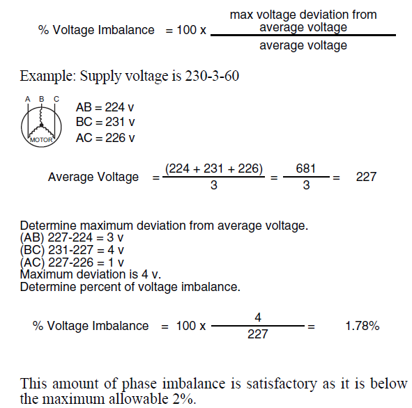
You can use this formula below to determine the percentage of voltage imbalance coming to a unit, or the voltage going to the motor or compressor.

Diagram showing voltage imbalance calculation from three-phase supply readings and maximum deviation example.

As we discuss current imbalance, keep in mind that voltage imbalance will cause current imbalance. However, current imbalance will happen without a voltage imbalance. Current imbalance between any two legs of a three phase system should never be above 10%. What can cause the current imbalance? When there is a current imbalance, look for poor points on a contactor, loose crimp connectors, lugs on disconnects or corrosion. All this can cause high resistance on one leg of power in a three-phase unit. Current, like most things, will follow the path of least resistance. When this happens, the current will increase in the other two legs of power, causing the other two windings in the motor to generate more heat and eventually damaging the motor or compressor.


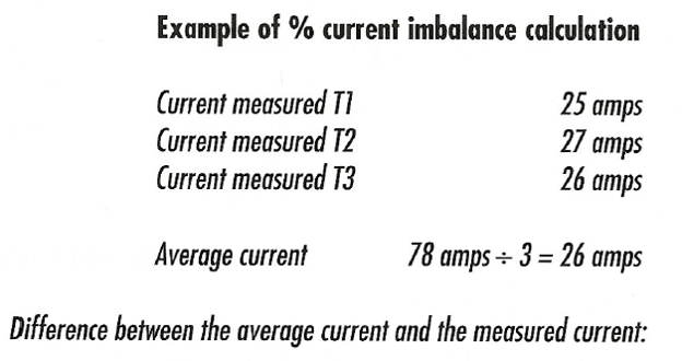
You can use this formula below to determine the percentage of current imbalance on the load side going to the equipment, motor or compressor.

Text diagram showing current imbalance calculation with T1 25 amps, T2 27 amps, T3 26 amps, average 26 amps.

Always keep in mind that the voltage to compressor terminals or motor connections during operation must be within voltage range indicated on unit nameplate. On three-phase units, voltages between phases must be balanced within 2%, and the current within 10%. Use the formulas above to determine the percent of voltage or current imbalance if there have been motor or compressor failures in a unit.


The voltage imbalance formula is in most three-phase installation instructions.


Sources:

48HC07-12 Installation Instructions

48TJ004-014 Product Data

HVAC SERVICING PROCEDURES


More to Explore

September 16, 2026
Disclaimer: The technical statements, information and recommendations contained herein are believed to be accurate as of the date hereof, but Mingledorff’s does not make representations or warranties, express or implied, as to its accuracy, its completeness, or the results to be obtained. The information is being provided for informational purposes only and is intended for use by persons having adequate skill and expertise regarding the proper selection, use and application of the products and recommendations and at their own risk and discretion. 
By Jesse Van Atta September 16, 2026
Disclaimer: The technical statements, information and recommendations contained herein are believed to be accurate as of the date hereof, but Mingledorff’s does not make representations or warranties, express or implied, as to its accuracy, its completeness, or the results to be obtained. The information is being provided for informational purposes only and is intended for use by persons having adequate skill and expertise regarding the proper selection, use and application of the products and recommendations and at their own risk and discretion.