It is a good practice to make sure all of your dip switches are set to the factory position on all of your flow selector boxes during installation. If the dip switches are not set in the factory position you will have L11 and E17 error codes to follow. You can verify the factory dip switch settings by looking at access door on the flow selector box. The L11 and E17 error codes can also be caused by wiring issues, good wiring practices can prevent having problems.
Changing dip switches on your flow selectors is not necessary because all of your flow selector addresses and port numbers are set using and codes 00FE and 0105 on your thermostat. Making sure your flow selector address and your flow selector port address is correct will make the start up process much easier. If care is taken and you have a good understanding of the wiring and installation of a VRF system the start up process can be close to seamless.
L11- Detected indoor unit address, Flow selector unit not connected.
E17- Communication trouble between indoor unit and flow selector unit.
Meter leads on the DFT position 1 and the C terminal.
Schematic: The circles represent where meter leads were making contact for testing.
The Pipe Sensor:
The pipe sensor monitors the temperature of the water going to a 2-pipe FCU, also known as changeover sensor, changeover switch, Aquastat, among others:
- If the water is hot (> 83 F), it signals the thermostat that the system is in heat mode;
- If the water is cold (< 65 F), it signals the thermostat that the system is in cooling mode;
- User configurable for Open or Closed activation
- Compatible with both on-Cool / on-Heat sensors (determined on 1st run setup)
- Compatible with dry-contact pipe sensors (on/off), not analog. (ex. 10K ohm thermistor)
- Dehumidify with Fan (Yes or No): when Dehum is active this setting specifies if you want the furnace/air-handler fan to run as well. This will activate (G) output on the t-stat at the same time. This can work independent of a cooling cycle.
- Min Runtime Delta (2-10%): to reduce short cycling, the dehumidifier will run beyond the desired humidity by the selected amount (%). Default is 5%.
- Dehumidify in Heat Mode (Yes or No): If humidity is a concern during the heating season and have a standalone Dehumidifier, this setting can be used to activate the Dehumidifier and will work independent of a heating cycle.
- Dehumidifier Active (Open or Closed): this setting is dependent whether the HVAC system or standalone Dehumidifier requires it to be open or closed while active. This setting is part of the 1st run setup but can change afterwards in the Dehumidifier menu.
Find the service literature for your specific outdoor unit. The compressor model numbers, and ohm values are published in every service manual for these units. Match your numbers to the chart provided on the back of the PBA and table below.
Or, if you prefer the hard way, just check the numbers on the compressor. Unfortunately, the model tags are facing the inside of the unit. You can try to get your camera phone in there and get a photo or use your mirror from your torch set and a flashlight to see back there and verify the model. Then set the SW1 dipswitches accordingly. See table below.

November 15, 2023
Communication is Key – Pt. 2
What exactly does no communication mean regarding Infinity and Evolution equipment? No communication means there is no clear signal of information received by the UI (User Interface), or it has been interrupted.
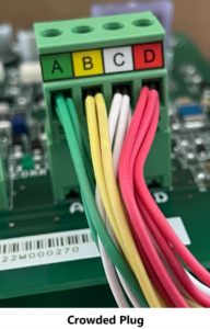
When no communication faults occur, there is a process that simplifies diagnosing the issue. Always start with the basics. Loose control wires in wire nut connections, ABCD plugs or UIs not seated perfectly, and crowded terminals can cause issues in a communicating system. Control wires running alongside or across high voltage wires can receive interference from the EM (electromagnetic) field generated by the current (amperage) from the power wires. Generally, control wires should be kept away from high voltage wires. If this is unavoidable, it is recommended to use a shielded stranded cable for the AB circuit and ground the cable on one end. Issues from interference are uncommon, but should be considered during the diagnosis.
Look for signs of moisture, especially inside of horizontal fancoils. Dirty power from wet electrical connections, as well as water damage to transformers and PC boards can cause poor communication or false codes to be generated. Many horizontal right fancoils are installed with high voltage wires entering directly above the control board. When this penetration is not sealed, there is potential for hot and/or humid air to mix with cool air inside the cabinet. This can be a source of intermittent fault codes as water condenses and drips down onto the board, then runs off and the code clears.
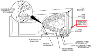
For all Infinity and Evolution model FE 002, 005, and 006 fancoils installed horizontal right, it is imperative to correctly “flip” the air seal assembly at the top of the coil, and relocate the drain pan support bracket to its proper location. Either of these two items missed or done incorrectly will eventually make for a water filled cabinet with completely saturated insulation. This results in an extremely wet environment inside the fancoil and will wreak havoc on all internal electrical components. Also, it can cause the exterior of the cabinet to sweat, which has its own set of issues.
Tips and tricks:
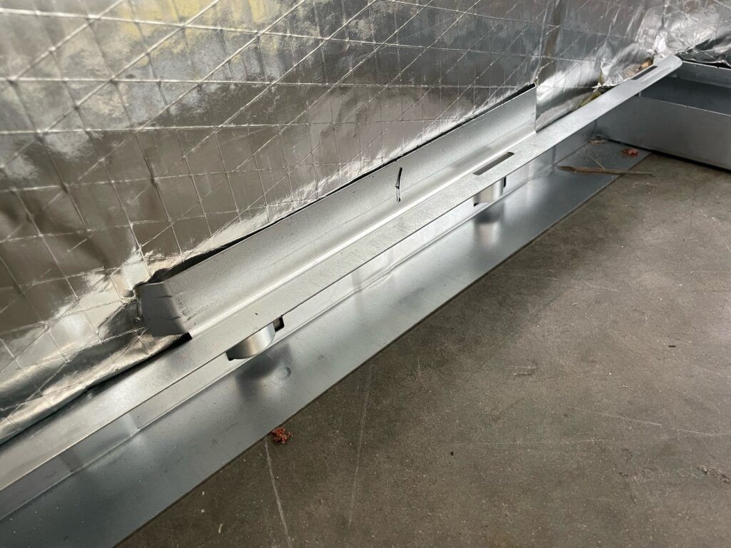
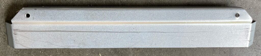
Once a cabinet is soaked, it is easy to diagnose these problems as resulting from a clogged drain line, leading to the wrong repair, and then a callback. This can happen to all Carrier, Bryant, or WeatherMaker fancoil models with an “A” coil. See below forsnippets from the installation manual and photos of the support bracket.


Remove horizontal drain pan support bracket from coil support rail on left side of unit and reinstall on coil support rail on right side of unit.

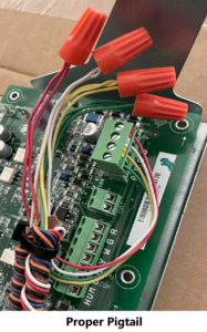
If inside the cabinet is dry, then verify all connections are good. Redo any crowded plug or terminal by making a pigtail in the control wire. It is recommended to only have one wire under each terminal. Another thing to look for is improperly stripped wires that are scored too deeply by wire strippers. If poor installation practices are suspected at all, then do yourself a favor and remake all connections.


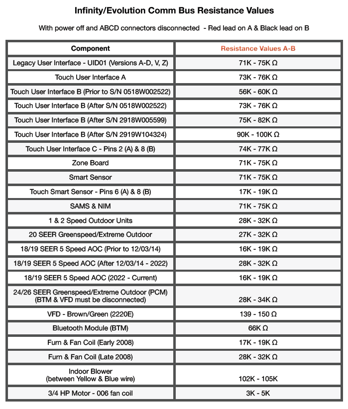
Once you have verified that all wires and connections are good, it is time to take the next step in diagnosis. Know your ohm values. Each communicating component has a specific ohm resistance range at their comm bus. Please see the chart at the end of this article for up-to-date ohm values. If all components read correctly, then the control wire(s) could be the issue. Read from the other end of the control wires and ohm through them back to each component. Any difference from your original readings indicates a flaw in the wire.
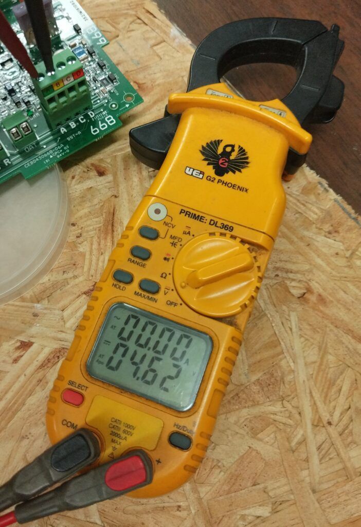
If all these possibilities have been eliminated, then advanced diagnosis is all that remains. Most Infinity and Evolution PC boards with power applied have a resting voltage of approximately 4.5-4.6 VDC on the AB pins. Specific exceptions to this rule are the early generation and current versions of 18 and 19 SEER five speed AOC boards, which have a resting 2.8 VDC, and can be identified by a lower 16-19K ohm value at the comm bus. AOC produced between December 2014 and early 2022 ohm between 28-32K and will have a resting 4.5-4.6 VDC.

Tips and tricks:
Communication is active when the UI is connected. Disconnect the UI to put the circuit at rest. It may be easier to identify what component is the issue with communication at rest versus fluctuating.
A resting voltage of 3.2 VDC or less on a system is the borderline of no communication. Comm voltage being dragged down can cause all sorts of intermittent issues, such as touchscreen UI’s becoming non-responsive, or momentary fault codes to be generated. Similar to checking ohms across the control wire, its integrity can also be checked by measuring resting VDC at the components and at the other end of the wire. A small drop of voltage of less than 1 VDC is acceptable across long lengths. If a drop of more than 1 VDC is found, the wire is likely compromised and pulling a new wire is recommended.
When a Carrier Infinity or Bryant Evolution system is communicating across all components, the VDC is constantly fluctuating. A range between .8-4.5 VDC may be seen on your digital meter in momentary flashes. An analog meter will show this as a bouncing of the needle. If problem components or wires are dragging down the communication, it can go into the millivolt range. When 24 VAC loads – such as contactor coils, gas valve solenoids, or heat relay coils – are engaged on a system running with low comm voltage, it can be the “straw that broke the camel’s back”. When these loads engage it can cause momentary no communication faults to occur, followed by the system dropping out, and then, the cycle repeats as everything comes back online. One must be methodical to find the issue. While measuring comm volts, begin a process of elimination.
The following is a real-life example from the field:
A 24 SEER heat pump system with two zones has a recurring indoor communication fault which always happens on the coldest nights. It is determined the event occurs shortly after the system engages heat strips due to going through a defrost cycle. Properly made connections, and ohm values of each component are confirmed to be good. However, comm volts are fluctuating in the millivolt range.
The process of elimination with power applied and communication active is started at the fancoil PC board. First, the blower communication wire is unplugged from the board, but the low comm remains. Next, the blower is plugged back in, and the tstat wire from the fancoil to the zone damper control and smart sensor is disconnected, but the low comm still remains. The zoning is reconnected, and then the outdoor unit wire is disconnected. Immediately, the comm volts return to normal, and the issue is isolated to the outdoor unit. The wire to the outdoor is reconnected at the fancoil. This wire had already been verified to be good, but to verify again, the AB plug is disconnected from the outdoor PCM. Comm volts return to normal and the control wire is eliminated as the problem, leaving only the heat pump as the source of the issue.
Instinct would be to condemn the outdoor PCM. However, there are three different communicating components in the outdoor unit: the PCM, the Bluetooth module, and the VFD. The AB plug is connected back to the PCM. The VFD comm wire is disconnected, but the low voltage remains. The VFD is connected back and then the Bluetooth module is disconnected from the PCM. The comm volts return to normal, and thus the Bluetooth module is identified as the source of the problem. A new Bluetooth module is installed and updated through the Carrier Service Tech app, which should be done every time a component is replaced on 24/26 SEER units. The system is put through a full reinstallation at the UI (which should be done every time a communicating component is replaced). The system is checked out first in heat strip mode, and then in heat mode with a forced defrost to verify it is working properly. Finally, all functions of the rest of the system are checked and found to be good.
Learning these methods and how to use this knowledge is key to being efficient at diagnosing Infinity and Evolution communication problems. Hopefully, this article has helped you have better understanding when it comes time to diagnosing various communication issues you may encounter in the field.

Disclaimer: The technical statements, information and recommendations contained herein are believed to be accurate as of the date hereof, but Mingledorff’s does not make representations or warranties, express or implied, as to its accuracy, its completeness, or the results to be obtained. The information is being provided for informational purposes only and is intended for use by persons having adequate skill and expertise regarding the proper selection, use and application of the products and recommendations and at their own risk and discretion.
More to Explore