It is a good practice to make sure all of your dip switches are set to the factory position on all of your flow selector boxes during installation. If the dip switches are not set in the factory position you will have L11 and E17 error codes to follow. You can verify the factory dip switch settings by looking at access door on the flow selector box. The L11 and E17 error codes can also be caused by wiring issues, good wiring practices can prevent having problems.
Changing dip switches on your flow selectors is not necessary because all of your flow selector addresses and port numbers are set using and codes 00FE and 0105 on your thermostat. Making sure your flow selector address and your flow selector port address is correct will make the start up process much easier. If care is taken and you have a good understanding of the wiring and installation of a VRF system the start up process can be close to seamless.
L11- Detected indoor unit address, Flow selector unit not connected.
E17- Communication trouble between indoor unit and flow selector unit.
Once you have logged in, you will need to save the equipment current configurations by choosing: “SAVE CONFIGS TO A FILE”. Align the arrow on the SAVE CONFIGS TO FILE option and press ENTER. Then press ENTER to make the STOP flash, use the UP or DOWN arrows to change the STOP to START and press ENTER. Once this is done, Choose Option 5 to UPGRADE SOFTWARE. Then scroll down to “FIND APPLICATION FILE” and press ENTER to change NO to YES.
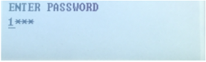
Then press ENTER to choose the USB Product Folders:
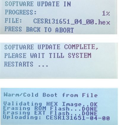
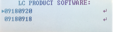
Then select the Product Software: Once selected press ENTER.

February 14, 2024
Freeze Protection mode
With outdoor air temps dropping below freezing around Georgia and the southeast, there is a chance you have walked by a 30 series chiller that was indicating (ALARMS) saying the phrase Freeze Protection Alarm has been activated.

Freeze Protection Alarm description, pulled directly form the manual:
“Coolers can be ordered with heaters installed in the factory. If equipped, the main base board based on the outdoor-air temperature and the entering and leaving water thermistors controls the cooler heaters. The Heater Set Point is the sum of the freeze point and Cooler Heater DT Setup (Configuration>SERV>HTR). If the entering or leaving water temperature is less than the Heater Set Point and the outdoor-air temperature is less than the Heater Set Point – 2°F (1.1°C), then the heater will be turned on. If the Entering or Leaving Water Temperature is less than the Brine Freeze Setpoint (Configuration>SERV>LOSP) + 1.0°F (0.5°C), then the heater will be turned on along with the pump.

If the cooler PUMP/PUMPS are not hard wired to the chiller control panel, this most important feature of the Carrier freeze protection routine is disabled.
In addition to the cooler PUMP freeze protection routine, the entire cooler is covered with closed-cell insulation applied over the heater.
Heater, plus pump control, plus insulation protect cooler against low ambient temperature freeze-up to –20°F (–28°C).

The Chiller control system will try to protect the barrel from freezing in very low ambient conditions. This is not the best way to combat Freeze issues if your machine is running fresh water.
The best 2 methods are either draining the chiller of all water when it’s not in use or adding an antifreeze to the chilled water loop, suitable to Protech against your outside air temps.
Disclaimer: The technical statements, information and recommendations contained herein are believed to be accurate as of the date hereof, but Mingledorff’s does not make representations or warranties, express or implied, as to its accuracy, its completeness, or the results to be obtained. The information is being provided for informational purposes only and is intended for use by persons having adequate skill and expertise regarding the proper selection, use and application of the products and recommendations and at their own risk and discretion.
More to Explore