
Kevin Thigpen

Technical Services Manager North Alabama District

August 18, 2025

How to Wire and Check a Dissipation Board

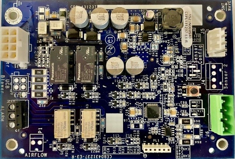
Blue printed circuit board with chips, capacitors, connectors, and a green terminal block on the right.

In our last article, Understanding Active Dissipation, we covered the basic reasons why a system may have a refrigerant leak and how the board will operate during dissipation mode due to that leak. This month we will take a deeper look at how to properly wire {install} and troubleshoot the sensor itself on the FJ fan coils.

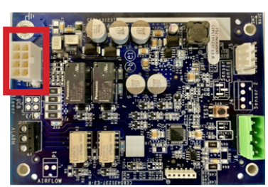
Blue circuit board with a red highlight box around a beige connector on the left side

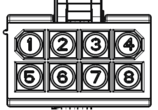
To be able to accurately troubleshoot anything, you must know where to start. The dissipation board pictured above, resides between the main board and the thermostat. This allows the dissipation system to actively control the unit during a dissipation sequence. This occurs starting at the wiring for the 8-pin plug on the dissipation board.


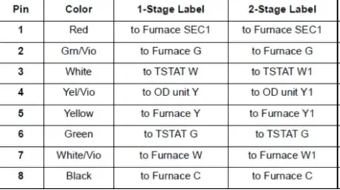
In the picture below is the proper wiring setup and color codes for each pin.

Wire pinout table listing 8 pins with colors and 1-stage/2-stage furnace thermostat connections.
Black-and-white diagram of an 8-button panel labeled 1 to 8 in two rows.

Note on communicating units: wires 3-7 will not be used. Only wires 1, 2 and 8 will be connected.

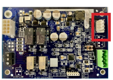
Blue circuit board with components, red-highlighted connector on the right edge

Next is the Dissipation Sensor. The sensor is a 4 pin 5vdc sensor with an 8ft harness. The sensor will be factory mounted in all fan coils and SPPs. The sensor will be located in the case coil boxing. If a cased coil is being installed, the sensor is NOT factory installed but does come included. Please be sure to check all packing materials to ensure the sensor and harness aren’t accidentally discarded.


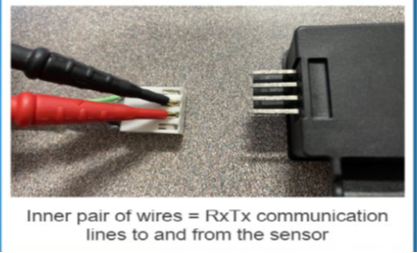
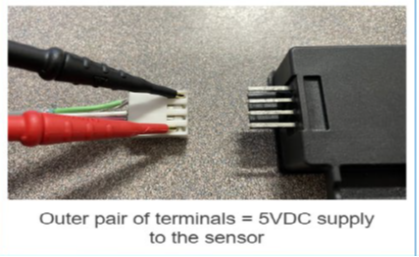
Troubleshooting the harness connections is simple using the picture below to check for the proper 5VDC signal.

Close-up of red and black wires connected to a small plug beside a black connector, with communication labels.
Red and black probes beside a 4-pin connector; caption notes outer terminals provide 5VDC to the sensor
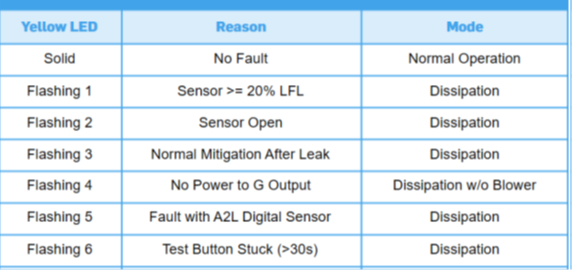
Blue troubleshooting table for yellow LED states, reasons, and modes of operation

Dissipation error code table:

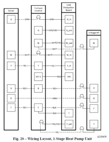
Technical wiring diagram showing layout of 3-stage heat pump unit with furnace control and thermostat connections
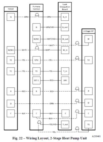
Wiring diagram showing a 2-stage heat pump unit with numbered terminals and dashed connection lines

This information should help with wiring and checking your dissipation board and sensor. Depending on the equipment, wiring may differ depending on the options being installed. Check both installation and service manuals for the equipment you are working with to verify proper wiring and functionality of the dissipation safety system.


Should you have any questions, please feel free to reach out to your local Mingledorff’s for help.


Disclaimer: The technical statements, information and recommendations contained herein are believed to be accurate as of the date hereof, but Mingledorff’s does not make representations or warranties, express or implied, as to its accuracy, its completeness, or the results to be obtained. The information is being provided for informational purposes only and is intended for use by persons having adequate skill and expertise regarding the proper selection, use and application of the products and recommendations and at their own risk and discretion.


More to Explore

September 16, 2026
Disclaimer: The technical statements, information and recommendations contained herein are believed to be accurate as of the date hereof, but Mingledorff’s does not make representations or warranties, express or implied, as to its accuracy, its completeness, or the results to be obtained. The information is being provided for informational purposes only and is intended for use by persons having adequate skill and expertise regarding the proper selection, use and application of the products and recommendations and at their own risk and discretion. 

By Jesse Van Atta September 16, 2026
Disclaimer: The technical statements, information and recommendations contained herein are believed to be accurate as of the date hereof, but Mingledorff’s does not make representations or warranties, express or implied, as to its accuracy, its completeness, or the results to be obtained. The information is being provided for informational purposes only and is intended for use by persons having adequate skill and expertise regarding the proper selection, use and application of the products and recommendations and at their own risk and discretion.