It is a good practice to make sure all of your dip switches are set to the factory position on all of your flow selector boxes during installation. If the dip switches are not set in the factory position you will have L11 and E17 error codes to follow. You can verify the factory dip switch settings by looking at access door on the flow selector box. The L11 and E17 error codes can also be caused by wiring issues, good wiring practices can prevent having problems.
Changing dip switches on your flow selectors is not necessary because all of your flow selector addresses and port numbers are set using and codes 00FE and 0105 on your thermostat. Making sure your flow selector address and your flow selector port address is correct will make the start up process much easier. If care is taken and you have a good understanding of the wiring and installation of a VRF system the start up process can be close to seamless.
L11- Detected indoor unit address, Flow selector unit not connected.
E17- Communication trouble between indoor unit and flow selector unit.
Meter leads on the DFT position 1 and the C terminal.
Schematic: The circles represent where meter leads were making contact for testing.
The Pipe Sensor:
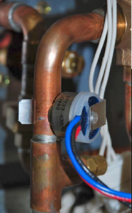
The pipe sensor monitors the temperature of the water going to a 2-pipe FCU, also known as changeover sensor, changeover switch, Aquastat, among others:
- If the water is hot (> 83 F), it signals the thermostat that the system is in heat mode;
- If the water is cold (< 65 F), it signals the thermostat that the system is in cooling mode;
- User configurable for Open or Closed activation
- Compatible with both on-Cool / on-Heat sensors (determined on 1st run setup)
- Compatible with dry-contact pipe sensors (on/off), not analog. (ex. 10K ohm thermistor)
- Dehumidify with Fan (Yes or No): when Dehum is active this setting specifies if you want the furnace/air-handler fan to run as well. This will activate (G) output on the t-stat at the same time. This can work independent of a cooling cycle.
- Min Runtime Delta (2-10%): to reduce short cycling, the dehumidifier will run beyond the desired humidity by the selected amount (%). Default is 5%.
- Dehumidify in Heat Mode (Yes or No): If humidity is a concern during the heating season and have a standalone Dehumidifier, this setting can be used to activate the Dehumidifier and will work independent of a heating cycle.
- Dehumidifier Active (Open or Closed): this setting is dependent whether the HVAC system or standalone Dehumidifier requires it to be open or closed while active. This setting is part of the 1st run setup but can change afterwards in the Dehumidifier menu.
January 12, 2024
Servicing Carrier VRF Part 1
You get to a school with a Carrier VRF system having issues. It’s large and intimidating. There’s an error code on the thermostat. What does it mean? How do I fix it? Scary situation if you aren’t prepared for it.
VRF isn’t so scary once you know what you’re looking for. When taking a call on the technical support line for VRF systems I commonly get asked what certain error codes are or how to diagnose an issue on a VRF system. These questions can often be diagnosed with the STT (Service Technical Tool) software supplied for free from Carrier on HVACpartners.com. Gone is the way of just a contactor and some pressure switches. With the direction technology and efficiency standards are going, HVAC systems are getting more and more electronics.
You have the software, now what? The first thing you need to know is how to hook up to the system itself. Unfortunately, these systems don’t work off Bluetooth yet. However, there are 2 different ways to hook up your computer to the system. This information is very valuable after all.
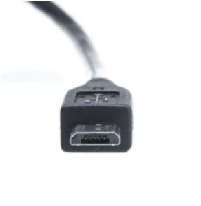
1. A MICRO USB cable. This cable is one you probably have in your trucks to charge various devices including flashlights, tablets, etc. The cable itself must be able transmit data and not just a charging cable. These can be picked up from nearly every local gas station, hardware store, or found online very easily. Cheap and easy.

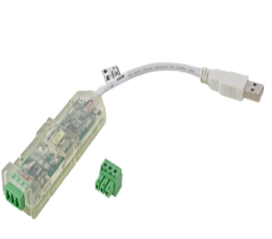
2. RS485 to USB adapter. If you’ve worked on I-Vu in the past, you probably already have one of these in your bag. This is a little more complicated to acquire than a Micro USB cable but opens your ability to attach inside the building at a Central Touchscreen communication line. These can be purchased via your favorite local HVAC supply house, Mingledorff’s.

*Note that these tools may need to be ordered so it’s best to be prepared ahead of time.

So now we have the software and the cables.
Where do they go?
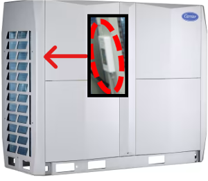
The Micro USB port is accessed behind the left front corner panel of the Outdoor Unit (ODU) at the bottom right of the spot check board.
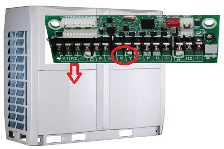
RS485 allows you to access the system via the communication bus on X and Y on the main board of the ODU or at the Central Controller inside the building. This is valuable as you can stay inside instead of going up and down to the roof to check your computer.
RS485 is polarity sensitive. X is 1 and Y is 2.

Now you are ready to start collecting the data needed.
Next newsletter we will cover how to use the software itself. What do you look for? How do I know what to do? I have an error, what does it mean? How do I correct it?
Disclaimer: The technical statements, information and recommendations contained herein are believed to be accurate as of the date hereof, but Mingledorff’s does not make representations or warranties, express or implied, as to its accuracy, its completeness, or the results to be obtained. The information is being provided for informational purposes only and is intended for use by persons having adequate skill and expertise regarding the proper selection, use and application of the products and recommendations and at their own risk and discretion.
More to Explore