It is a good practice to make sure all of your dip switches are set to the factory position on all of your flow selector boxes during installation. If the dip switches are not set in the factory position you will have L11 and E17 error codes to follow. You can verify the factory dip switch settings by looking at access door on the flow selector box. The L11 and E17 error codes can also be caused by wiring issues, good wiring practices can prevent having problems.


Changing dip switches on your flow selectors is not necessary because all of your flow selector addresses and port numbers are set using and codes 00FE and 0105 on your thermostat. Making sure your flow selector address and your flow selector port address is correct will make the start up process much easier. If care is taken and you have a good understanding of the wiring and installation of a VRF system the start up process can be close to seamless.


L11- Detected indoor unit address, Flow selector unit not connected.


E17- Communication trouble between indoor unit and flow selector unit.

Meter leads on the DFT position 1 and the C terminal.


Schematic: The circles represent where meter leads were making contact for testing.

The Pipe Sensor:
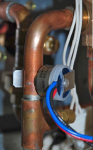
Copper pipes and a blue wire connected to a small electrical component in a mechanical setup

The pipe sensor monitors the temperature of the water going to a 2-pipe FCU, also known as changeover sensor, changeover switch, Aquastat, among others:


  • If the water is hot (> 83 F), it signals the thermostat that the system is in heat mode;
  • If the water is cold (< 65 F), it signals the thermostat that the system is in cooling mode;
  • User configurable for Open or Closed activation
  • Compatible with both on-Cool / on-Heat sensors (determined on 1st run setup)
  • Compatible with dry-contact pipe sensors (on/off), not analog. (ex. 10K ohm thermistor)
  • Dehumidify with Fan (Yes or No): when Dehum is active this setting specifies if you want the furnace/air-handler fan to run as well. This will activate (G) output on the t-stat at the same time. This can work independent of a cooling cycle.
  • Min Runtime Delta (2-10%): to reduce short cycling, the dehumidifier will run beyond the desired humidity by the selected amount (%). Default is 5%.
  • Dehumidify in Heat Mode (Yes or No): If humidity is a concern during the heating season and have a standalone Dehumidifier, this setting can be used to activate the Dehumidifier and will work independent of a heating cycle.
  • Dehumidifier Active (Open or Closed): this setting is dependent whether the HVAC system or standalone Dehumidifier requires it to be open or closed while active. This setting is part of the 1st run setup but can change afterwards in the Dehumidifier menu.

Find the service literature for your specific outdoor unit. The compressor model numbers, and ohm values are published in every service manual for these units. Match your numbers to the chart provided on the back of the PBA and table below.


Or, if you prefer the hard way, just check the numbers on the compressor. Unfortunately, the model tags are facing the inside of the unit. You can try to get your camera phone in there and get a photo or use your mirror from your torch set and a flashlight to see back there and verify the model. Then set the SW1 dipswitches accordingly. See table below.
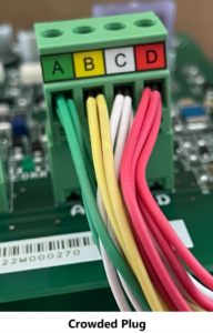
Crowded multicolor wire plug connected to green circuit board terminals labeled A, B, C, D

Once signed into your account, touch “Connect to Outdoor Unit or Furnace”. This will take you to the “Connect to Equipment” screen. Select “Outdoor Unit (Bluetooth)” and the app will search for equipment.

Jesse Van Atta

VRF Quality Assurance Manager Gulf Coast District

August 10, 2023

The Magic Is In The Change

What is superheat? What is sub–cooling? In this article we will review what refrigeration is, how it works, and some of the terminology. Hopefully, it will help you troubleshoot problems within the basic refrigerant circuit, and then apply these skills to more complex systems. For newcomers to the trade, this basic knowledge is critical. For seasoned veterans, a refresher never hurts.


The Basics


Refrigeration is the ability to move heat from a place it is not desired to one where it is unopposed. An air conditioner does not actually cool a space, rather it removes heat from it. This happens by utilizing the changes of state in refrigerant between liquid and vapor to reject and absorb heat. Refrigerants can be many things from water to CO2, or chemicals such as R410A, which is common in current residential and light commercial applications. Some refrigerants work better in specific temperature ranges and environments than others, but regardless of the type, the principles of refrigeration remain the same.


The Four Major Components of Refrigeration

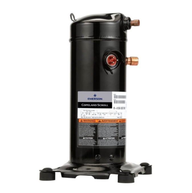
1. Compressor: This is the heart of the system. Named for the job it performs, it compresses the low-pressure vapor into high-pressure vapor (discharge) and pumps the refrigerant through the system. 

Black cylindrical refrigeration compressor with copper ports and labels on a white background

Compressor

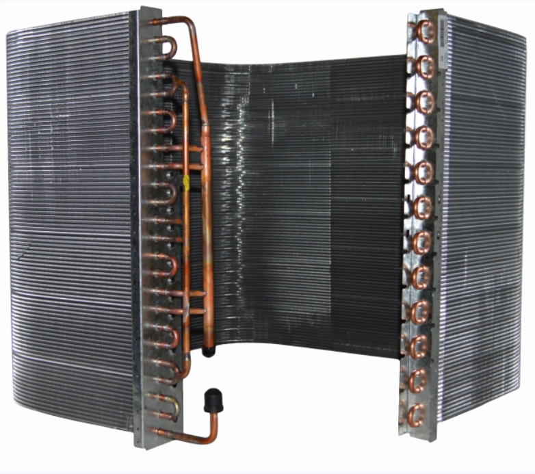
2. Condenser: Half the magic happens here as high-pressure vapor pumped from the compressor rejects heat until it has changed state and condensed into a high-pressure sub–cooled liquid.

Copper HVAC evaporator coil with black fins and aluminum end plates, shown in a U-shape.

Condenser Coil

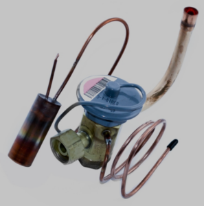
3. Metering device: This is where the refrigerant drops from high to low pressure and transforms to a mostly liquid with some vapor (mixed phase) state. Also, it regulates the flow of refrigerant through the evaporator.

Set of HVAC refrigeration parts: blue valve, copper tubes, and a small cylindrical component.

TXV

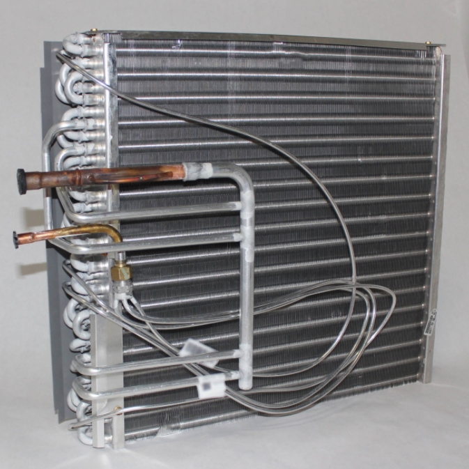
4. Evaporator: The other half of the magic happens here as low-pressure liquid absorbs heat and changes state to a low-pressure superheated vapor. This vapor then returns to the compressor through the suction line.

Metal HVAC evaporator coil with copper tubing and gray fins on a white background

Evaporator Coil

The Refrigeration Cycle in Action

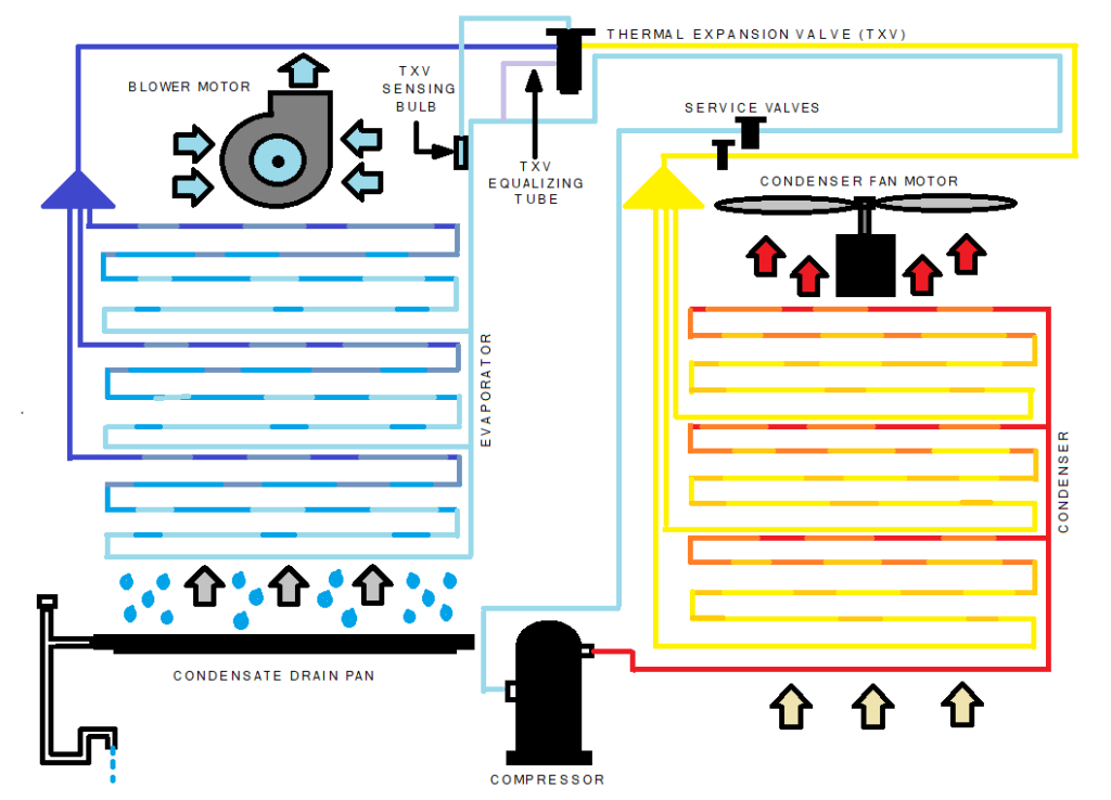
Annotated engineering diagram with blue and yellow airflow paths, arrows, and labeled components.

In the graphic, the red refrigerant line represents high-pressure vapor from the compressor. As this discharge vapor flows through the condenser, it rejects heat into the air, gradually changing state to a high-pressure liquid. This change is represented by colors transitioning from red to orange. The refrigerant continues to reject heat, becoming a liquid that is sub–cooled beyond its saturation point, shown in yellow. Then it flows to the metering device (TXV), which provides the drop in temperature and pressure. On the outlet side of the TXV, the refrigerant has transformed to a low-pressure, mostly liquid (mixed phase) state, represented by dark blue. As air is pulled across the coil by the blower, heat is absorbed from the air into the refrigerant causing it to change state from liquid to vapor, represented by the colors transitioning from grey to blue. The pale blue line represents superheated vapor that has absorbed heat beyond its saturation point.


Tips and Tricks: Latent Heat as Humidity


It is important to note that a second process of heat removal occurs in the evaporator when its surface temperature is below dewpoint of the air passing across it. A space with high relative humidity (latent heat) will affect the system’s ability to remove sensible heat from the air. This must be considered when diagnosing an issue or trying to get a refrigerant charge exactly right. As the humidity of a space falls in line, the performance of sensible heat removal will improve.


Why the Magic is in the Change


The HVACR industry almost exclusively uses the BTU (British thermal unit) as its measurement of heat. One BTU is the amount of heat or energy required to raise one pound of water by one degree Fahrenheit. This is a constant while the water remains a liquid between 32F and 212F. To transform this water into one pound of 212F vapor, it requires significantly more energy at 970 BTUs. Most of the work happens during the change of state. This principle is utilized in refrigeration by designing a system that can force the changes of state of a refrigerant from vapor to liquid, and then back to vapor again to move heat where we want it to go.


A Review of Terminology


  • Discharge is the high-pressure hot gas (vapor) refrigerant as it leaves the compressor. It maintains the superheat carried over from the suction. If it exceeds 225F, then the compressor oil may breakdown causing an eminent lubrication failure. Most compressors have an internal thermal switch that will open before it reaches critical temperatures.
  • Liquid is the sub-cooled refrigerant as it leaves the condenser after it has rejected enough heat to change state from a high-pressure vapor. Also, it is the state of low-pressure refrigerant leaving the metering device before it absorbs enough heat to change to a low-pressure vapor in the evaporator.
  • Suction is the low-pressure superheated vapor as it leaves the evaporator and travels to the compressor. A TXV type metering device uses a sensing bulb charged with the same refrigerant as the system to open or close, as needed, to keep an optimal amount of refrigerant moving through the evaporator coil.
  • Saturation is the specific temperature of a refrigerant at a specific pressure when in a resting condition. ***Tips and tricks: Knowing the exact temperature of a refrigerant drum (vs a PT chart) is a great way to calibrate the pressure on your gauges.
  • Superheat is the heat absorbed into a refrigerant above its saturated vapor point. This measurement tells how the evaporator is performing. High superheat means the liquid has boiled off too soon and the evaporator is starved for refrigerant. Little or no superheat means that the liquid is making it through the coil.
  • Sub-cooling is the heat rejected from a liquid refrigerant below its saturation point. This measurement tells how the condenser is performing. High sub-cooling means the refrigerant is backing up in the line from the metering device. Little or none means the high-pressure vapor from the compressor is not changing state properly.


Basic Refrigeration Diagnosis

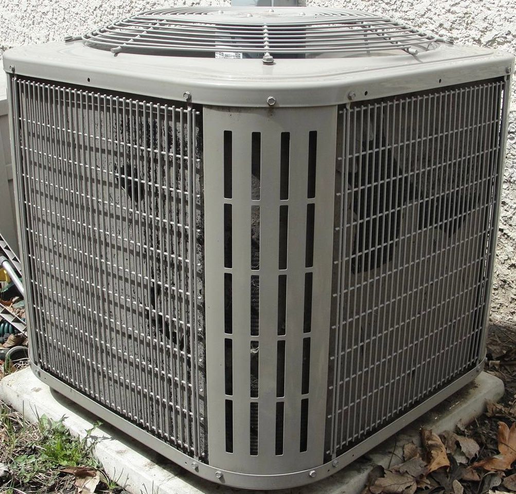
What Happens if Air is Restricted through the Outdoor Coil?


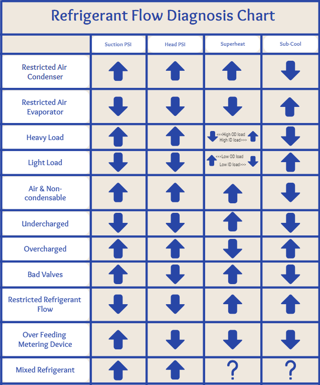
The high-pressure refrigerant is hindered from rejecting heat and changing state to a liquid. Suction, head (liquid) pressure will be elevated. Superheat will be high and there will be little to no sub-cooling.

Gray outdoor air conditioner unit with metal grille on a concrete pad

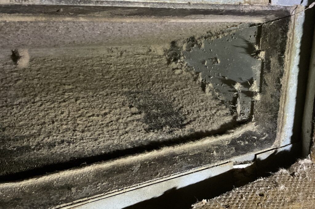
What Happens if Air is Restricted through the Indoor Coil?


The low-pressure liquid refrigerant is hindered from absorbing heat and changing state to a vapor. Suction and head pressures will be low with little to no superheat and elevated sub-cooling.

Dusty, damaged window screen or vent frame with torn mesh and dirt buildup

Dirty Evap Coil

How Does a Heavy Ambient Load Affect my Readings?


Suction and head pressures will be elevated. Superheat will vary depending on indoor and outdoor conditions. Sub-cooling will usually be lower than normal.


How Does a Light Ambient Load Affect my Readings?


Suction and head pressure will be diminished. Superheat will vary depending on indoor and outdoor conditions. Sub-cool will usually be higher than normal.


How Can I Tell if I have Non-Condensables in the Refrigerant?


Suction and head pressures and will be elevated. Superheat will usually be high and Sub-cool low.


***Tips and Tricks: The best way to verify if you are dealing with non-condensables is to pump the system down. Once the refrigerant is isolated in the outdoor unit, unwire the compressor and run just the condenser fan for about 10 minutes to acclimate the refrigerant. Then compare your refrigerant pressure against a PT chart. If it is higher than the chart, you have non-condensables.


What Happens when the Refrigerant Charge is Low?


Suction and head pressure will be low because there is not enough refrigerant in the system to complete the changes of state in the condenser and evaporator. Superheat will be high. There will be little to no sub-cooling.


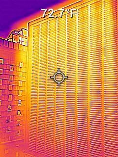
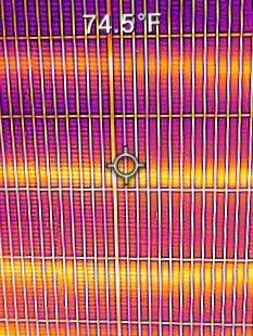
***Tips and Tricks: You can use a thermal camera to see if a condenser is sub-cooling the liquid. In the following photos, the two units on the top have little to no sub-cooling while the two on the bottom have proper sub-cooling, as shown by the banding of color.

Thermal view of a corrugated metal fence or gate beside a building, with a targeting reticle in the center.
Thermal image of a striped surface with a crosshair centered and temperature reading 74.3°F.

What Happens when the System is Over-Charged?


Suction and head pressure will be elevated. There will be little to no superheat. Sub-cooling will be high as the refrigerant molecules stack up on the inlet side of the metering device.


How Can I Tell I have Bad Valves in the Compressor?


Suction pressure will be elevated, and head pressure will be diminished. Superheat will be high. There will be little to no sub-cooling. ***Tips and tricks: Try to pump the system down. If the system will not pump down or stabilizes at a positive pressure, without trying to bypass refrigerant, it is likely the valves will have failed.


What Happens when the Metering Device gets Restricted?


Suction pressure will usually be lower than normal. Head pressure may be elevated. Superheat will be high. Sub-cooling will be high as refrigerant molecules stack up on the inlet side of the metering device.


What Happens when the System is Over-Metering?


Suction pressure will be high and head pressure will be low. There will be little to no superheat and sub-cooling. The causes for this depend on the type of metering device.


How Can I Tell if I Have Mixed Refrigerant?


Suction and head pressures are usually elevated. Depending on the mix of refrigerant, superheat and sub-cool are completely variable. ***Tips and Tricks: This diagnosis can apply to some blended refrigerants that become fractured.


An old, printed copy of the chart below helped me immensely at the beginning of my service career. I hope it can help you the way that it helped me….

Blue-and-white refrigerant flow diagnosis chart with up/down arrows for common HVAC problems

Disclaimer: The technical statements, information and recommendations contained herein are believed to be accurate as of the date hereof, but Mingledorff’s does not make representations or warranties, express or implied, as to its accuracy, its completeness, or the results to be obtained. The information is being provided for informational purposes only and is intended for use by persons having adequate skill and expertise regarding the proper selection, use and application of the products and recommendations and at their own risk and discretion.


More to Explore

September 16, 2026
Disclaimer: The technical statements, information and recommendations contained herein are believed to be accurate as of the date hereof, but Mingledorff’s does not make representations or warranties, express or implied, as to its accuracy, its completeness, or the results to be obtained. The information is being provided for informational purposes only and is intended for use by persons having adequate skill and expertise regarding the proper selection, use and application of the products and recommendations and at their own risk and discretion. 
By Jesse Van Atta September 16, 2026
Disclaimer: The technical statements, information and recommendations contained herein are believed to be accurate as of the date hereof, but Mingledorff’s does not make representations or warranties, express or implied, as to its accuracy, its completeness, or the results to be obtained. The information is being provided for informational purposes only and is intended for use by persons having adequate skill and expertise regarding the proper selection, use and application of the products and recommendations and at their own risk and discretion.