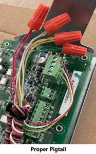
It is a good practice to make sure all of your dip switches are set to the factory position on all of your flow selector boxes during installation. If the dip switches are not set in the factory position you will have L11 and E17 error codes to follow. You can verify the factory dip switch settings by looking at access door on the flow selector box. The L11 and E17 error codes can also be caused by wiring issues, good wiring practices can prevent having problems.


Changing dip switches on your flow selectors is not necessary because all of your flow selector addresses and port numbers are set using and codes 00FE and 0105 on your thermostat. Making sure your flow selector address and your flow selector port address is correct will make the start up process much easier. If care is taken and you have a good understanding of the wiring and installation of a VRF system the start up process can be close to seamless.


L11- Detected indoor unit address, Flow selector unit not connected.


E17- Communication trouble between indoor unit and flow selector unit.

Meter leads on the DFT position 1 and the C terminal.


Schematic: The circles represent where meter leads were making contact for testing.

The Pipe Sensor:
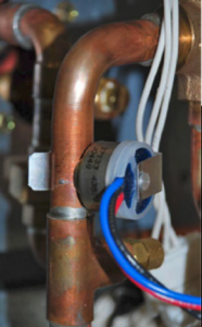
Copper plumbing pipes with a blue and red wire-connected sensor in a utility space

The pipe sensor monitors the temperature of the water going to a 2-pipe FCU, also known as changeover sensor, changeover switch, Aquastat, among others:


  • If the water is hot (> 83 F), it signals the thermostat that the system is in heat mode;
  • If the water is cold (< 65 F), it signals the thermostat that the system is in cooling mode;
  • User configurable for Open or Closed activation
  • Compatible with both on-Cool / on-Heat sensors (determined on 1st run setup)
  • Compatible with dry-contact pipe sensors (on/off), not analog. (ex. 10K ohm thermistor)
  • Dehumidify with Fan (Yes or No): when Dehum is active this setting specifies if you want the furnace/air-handler fan to run as well. This will activate (G) output on the t-stat at the same time. This can work independent of a cooling cycle.
  • Min Runtime Delta (2-10%): to reduce short cycling, the dehumidifier will run beyond the desired humidity by the selected amount (%). Default is 5%.
  • Dehumidify in Heat Mode (Yes or No): If humidity is a concern during the heating season and have a standalone Dehumidifier, this setting can be used to activate the Dehumidifier and will work independent of a heating cycle.
  • Dehumidifier Active (Open or Closed): this setting is dependent whether the HVAC system or standalone Dehumidifier requires it to be open or closed while active. This setting is part of the 1st run setup but can change afterwards in the Dehumidifier menu.

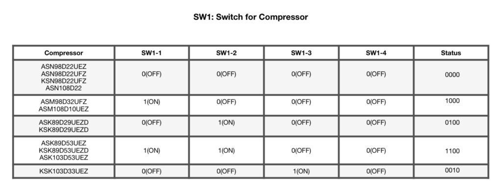
Find the service literature for your specific outdoor unit. The compressor model numbers, and ohm values are published in every service manual for these units. Match your numbers to the chart provided on the back of the PBA and table below.


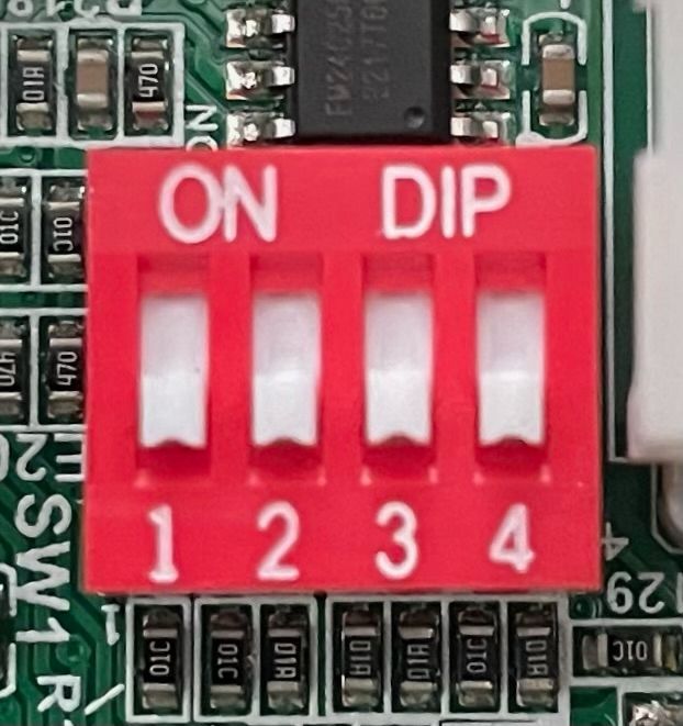
Or, if you prefer the hard way, just check the numbers on the compressor. Unfortunately, the model tags are facing the inside of the unit. You can try to get your camera phone in there and get a photo or use your mirror from your torch set and a flashlight to see back there and verify the model. Then set the SW1 dipswitches accordingly. See table below.

Jesse Van Atta

VRF Quality Assurance Manager Gulf Coast District

December 14, 2023

Universal PBA Inverter for 9 and 12K Btu Outdoor DLS

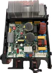
Historically, any dipswitch on a Carrier/Bryant mini split outdoor PC board were set by the factory and left alone. Now, for many of the outdoor units there are universal replacements. This PBA (Primary Board Assembly) Inverter will cover almost the entire ensemble of Carrier/Bryant ductless 9,000 and 12,000 Btu heat pumps and air conditioners. It makes a difference how you set the dipswitches

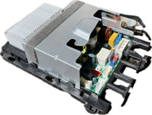
Electronic control module with silver heat sink and exposed internal circuit board on a white background

Part Number: 17222000A59952

Features of the new PBA Inverter


  • Capacity: 9-12K Btu
  • Power supply: 220V-240V, 1Ph, 50 or 60 Hz
  • Fan type: DC motor or AC motor
  • With or without electronic expansion valve
  • 11 different types of compressors
Open electronic control module with large silver heatsink and exposed circuit board components

What type of fan motor do you have?


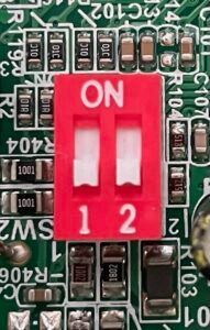
A DC fan motor will have only 3 wires and no capacitor. An AC motor will have 5 wires (3 to the motor and 2 to the capacitor). The universal PBA comes with an adapter plug and new capacitor for AC voltage motors. The plug locations on the board are specific to each motor. There are 2 dipswitches labeled SW2 for whichever one you have. In North America: for DC fan motors, both bit 1 and 2 should be off. For AC both bits should be on.

Red two-position DIP switch on a circuit board labeled ON and 1 2

What is your compressor model number? Finding this out can be easy or hard.


I vote easy! Use your handy dandy service tech app. Any version will do…

Three app icons on a gray background: Bryant, Carrier, and Replacement Components service tech apps.

Find the service literature for your specific outdoor unit. The compressor model numbers, and ohm values are published in every service manual for these units. Match your numbers to the chart provided on the back of the PBA and table below.


Or, if you prefer the hard way, just check the numbers on the compressor. Unfortunately, the model tags are facing the inside of the unit. You can try to get your camera phone in there and get a photo or use your mirror from your torch set and a flashlight to see back there and verify the model. Then set the SW1 dipswitches accordingly. See table below.
Close-up of a red 4-position DIP switch on a circuit board, labeled ON and 1–4.
Blurry black-and-white table with multiple columns and rows of text and numbers, likely a spreadsheet or report.

Everything else should be plug and play!

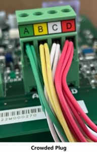
Crowded multicolor wires plugged into a green circuit board connector labeled A, B, C, D
Green circuit board with multicolored wires capped by red wire nuts labeled “Proper Pigtail”

Tips and tricks:


Take photos or good mental notes of the CN#(s) on each connector.

Some connectors can fit in places they don’t belong. However, they are color for color.


Disclaimer: The technical statements, information and recommendations contained herein are believed to be accurate as of the date hereof, but Mingledorff’s does not make representations or warranties, express or implied, as to its accuracy, its completeness, or the results to be obtained. The information is being provided for informational purposes only and is intended for use by persons having adequate skill and expertise regarding the proper selection, use and application of the products and recommendations and at their own risk and discretion.


More to Explore

September 16, 2026
Disclaimer: The technical statements, information and recommendations contained herein are believed to be accurate as of the date hereof, but Mingledorff’s does not make representations or warranties, express or implied, as to its accuracy, its completeness, or the results to be obtained. The information is being provided for informational purposes only and is intended for use by persons having adequate skill and expertise regarding the proper selection, use and application of the products and recommendations and at their own risk and discretion. 
By Jesse Van Atta September 16, 2026
Disclaimer: The technical statements, information and recommendations contained herein are believed to be accurate as of the date hereof, but Mingledorff’s does not make representations or warranties, express or implied, as to its accuracy, its completeness, or the results to be obtained. The information is being provided for informational purposes only and is intended for use by persons having adequate skill and expertise regarding the proper selection, use and application of the products and recommendations and at their own risk and discretion.