It is a good practice to make sure all of your dip switches are set to the factory position on all of your flow selector boxes during installation. If the dip switches are not set in the factory position you will have L11 and E17 error codes to follow. You can verify the factory dip switch settings by looking at access door on the flow selector box. The L11 and E17 error codes can also be caused by wiring issues, good wiring practices can prevent having problems.
Changing dip switches on your flow selectors is not necessary because all of your flow selector addresses and port numbers are set using and codes 00FE and 0105 on your thermostat. Making sure your flow selector address and your flow selector port address is correct will make the start up process much easier. If care is taken and you have a good understanding of the wiring and installation of a VRF system the start up process can be close to seamless.
L11- Detected indoor unit address, Flow selector unit not connected.
E17- Communication trouble between indoor unit and flow selector unit.
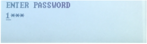
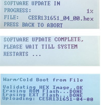
Once you have logged in, you will need to save the equipment current configurations by choosing: “SAVE CONFIGS TO A FILE”. Align the arrow on the SAVE CONFIGS TO FILE option and press ENTER. Then press ENTER to make the STOP flash, use the UP or DOWN arrows to change the STOP to START and press ENTER. Once this is done, Choose Option 5 to UPGRADE SOFTWARE. Then scroll down to “FIND APPLICATION FILE” and press ENTER to change NO to YES.
Then press ENTER to choose the USB Product Folders:
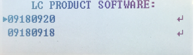
Then select the Product Software: Once selected press ENTER.

September 14, 2023
The Compressor is Not Starting
With technology advancing more and more every day, the days of relays to contactor style control are behind us. Carrier units with MBB boards have sensors everywhere from the suction pressor to Current sensors on the compressor. This does have a great benefit to having a unit in which you can attach one set of remote contacts then it will run. But this can cause issues once you start getting wear on the sensors. This can cause the codes P.16-P.27 which can cause massive headaches to hunt down.
The Code states the Compressor has not started or pressure has not been established. This Fault is read if the compressor discharge-suction did not increase 10 psig in 2 min. This goes back to the sequence of operation for the starting of the compressor. The sensor that makes a technician’s job easier on checking trails is also how the machine knows it’s doing what the MBB commands. This can affect the unit not being able to run at full capacity to shutting down whole circuits. This can come from faulty transducers to faulty current sensors. This will make the MBB Board think the compressor is not operating correctly
The potential fixes for this are very simple if you take it step by step. The first step is to verify the standing pressure. Use a set of gauges tied in the service ports next to the transducer. Once the gauges are installed use the Comfort Link to verify the pressures of the Gauges. If they are off more than 10 psi the bad transducer needs to be changed. If the transducer’s reading is good verify the control voltage to the contactors and make sure there is no loss going to the contactors from the MBB. Make sure you have the signal out of the scroll protection module. If those are present and the transducer is fixed the problem is solved.
Disclaimer: The technical statements, information and recommendations contained herein are believed to be accurate as of the date hereof, but Mingledorff’s does not make representations or warranties, express or implied, as to its accuracy, its completeness, or the results to be obtained. The information is being provided for informational purposes only and is intended for use by persons having adequate skill and expertise regarding the proper selection, use and application of the products and recommendations and at their own risk and discretion.
More to Explore



