It is a good practice to make sure all of your dip switches are set to the factory position on all of your flow selector boxes during installation. If the dip switches are not set in the factory position you will have L11 and E17 error codes to follow. You can verify the factory dip switch settings by looking at access door on the flow selector box. The L11 and E17 error codes can also be caused by wiring issues, good wiring practices can prevent having problems.


Changing dip switches on your flow selectors is not necessary because all of your flow selector addresses and port numbers are set using and codes 00FE and 0105 on your thermostat. Making sure your flow selector address and your flow selector port address is correct will make the start up process much easier. If care is taken and you have a good understanding of the wiring and installation of a VRF system the start up process can be close to seamless.


L11- Detected indoor unit address, Flow selector unit not connected.


E17- Communication trouble between indoor unit and flow selector unit.

Meter leads on the DFT position 1 and the C terminal.


Schematic: The circles represent where meter leads were making contact for testing.

The Pipe Sensor:
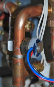
Copper pipe with gray valve and blue/red wires in a mechanical area

The pipe sensor monitors the temperature of the water going to a 2-pipe FCU, also known as changeover sensor, changeover switch, Aquastat, among others:


  • If the water is hot (> 83 F), it signals the thermostat that the system is in heat mode;
  • If the water is cold (< 65 F), it signals the thermostat that the system is in cooling mode;
  • User configurable for Open or Closed activation
  • Compatible with both on-Cool / on-Heat sensors (determined on 1st run setup)
  • Compatible with dry-contact pipe sensors (on/off), not analog. (ex. 10K ohm thermistor)
  • Dehumidify with Fan (Yes or No): when Dehum is active this setting specifies if you want the furnace/air-handler fan to run as well. This will activate (G) output on the t-stat at the same time. This can work independent of a cooling cycle.
  • Min Runtime Delta (2-10%): to reduce short cycling, the dehumidifier will run beyond the desired humidity by the selected amount (%). Default is 5%.
  • Dehumidify in Heat Mode (Yes or No): If humidity is a concern during the heating season and have a standalone Dehumidifier, this setting can be used to activate the Dehumidifier and will work independent of a heating cycle.
  • Dehumidifier Active (Open or Closed): this setting is dependent whether the HVAC system or standalone Dehumidifier requires it to be open or closed while active. This setting is part of the 1st run setup but can change afterwards in the Dehumidifier menu.

Find the service literature for your specific outdoor unit. The compressor model numbers, and ohm values are published in every service manual for these units. Match your numbers to the chart provided on the back of the PBA and table below.


Or, if you prefer the hard way, just check the numbers on the compressor. Unfortunately, the model tags are facing the inside of the unit. You can try to get your camera phone in there and get a photo or use your mirror from your torch set and a flashlight to see back there and verify the model. Then set the SW1 dipswitches accordingly. See table below.
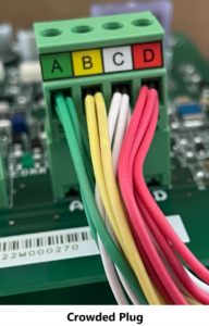

Color-coded wires crowded into a green PCB terminal block labeled A, B, C, D

Jesse Van Atta

VRF Quality Assurance Manager Gulf Coast District

September 13, 2023

Using Bluetooth on 24/26 SEER Carrier Equipment

The most current 24 and 26 SEER Carrier GREENSPEED and Bryant EXTREME offer a few upgrades from the original versions. Now, they have a capacity range from 25% to 100% and added a discharge pressure transducer to the ensemble of inputs for more protection and adjustment ability. Similar to the original Greenspeed and Extreme units, they provide a basic 24VAC transformer for power to the primary control module (PCM). Another upgrade is a communicating Bluetooth Module for monitoring performance and updating the components through the Carrier, Bryant, or Replacement Components Service Tech Apps. It is highly recommended to perform this update at the time of system commissioning and later during any service or maintenance performed to the equipment.


What is Bluetooth?


Bluetooth is a wireless technology used to exchange data between devices over short distances, mainly as an alternative to wired connections. It utilizes UHF radio waves with low transmission power, covering a max distance of about 33 feet.


What Apps Can I Use?

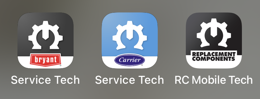
Three app icons on a gray background: Bryant Service Tech, Carrier Service Tech, and RC Mobile Tech.

Be aware that signing in as a guest will only give you limited ability with the apps.

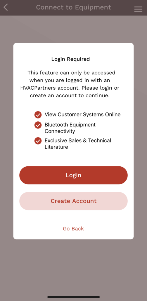
Mobile app signup/login screen with a white card, red buttons, and a top menu icon.
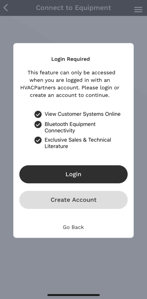
Mobile app signup screen with white card, bullet points, and Login and Create account buttons on gray background

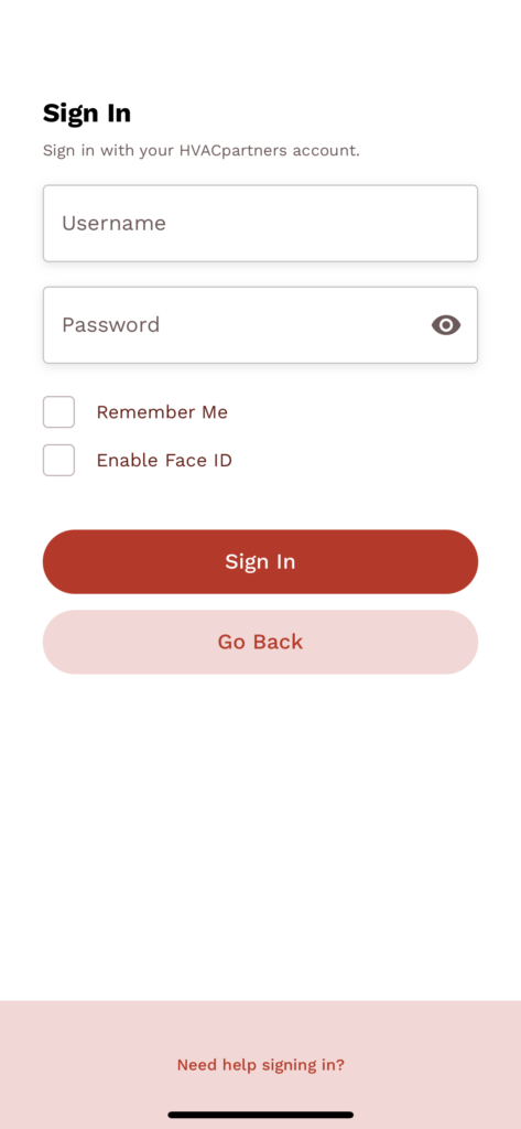
Sign in using your HVACPartners credentials to utilize the advanced features.

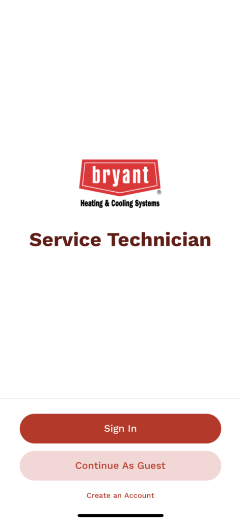
Bryant Service Technician screen with red sign-in buttons on a white background
Mobile sign-in screen with email and password fields, a red sign-in button, and a light pink secondary button.
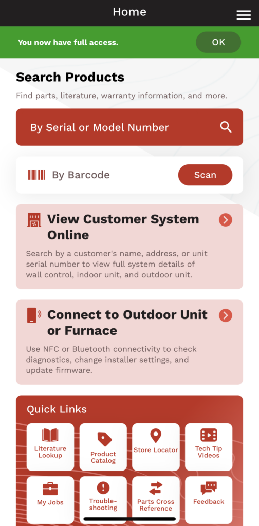
Mobile app home screen with search, customer system status cards, and quick links on a red-and-white interface

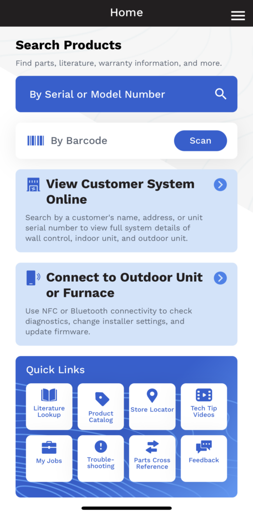
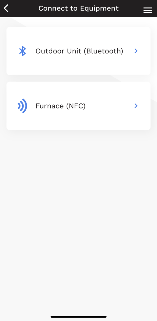
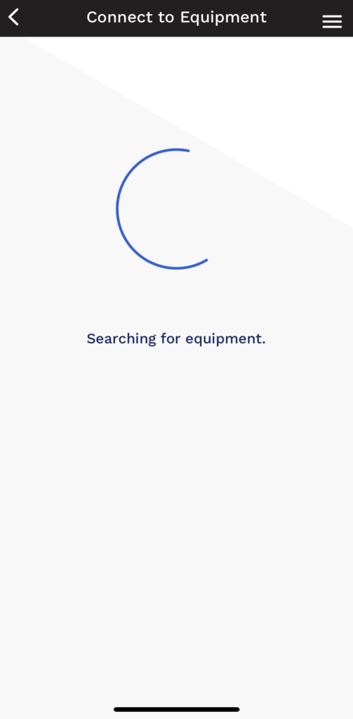
Once signed into your account, touch “Connect to Outdoor Unit or Furnace”. This will take you to the “Connect to Equipment” screen. Select “Outdoor Unit (Bluetooth)” and the app will search for equipment.

Mobile app home screen with search bar, promo cards, and quick-link icons on a blue background
Mobile app screen titled “Connect to Equipment” showing two Bluetooth device options.
Mobile app loading screen with blue spinner and “Searching for equipment” text

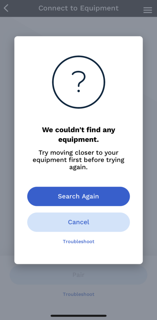
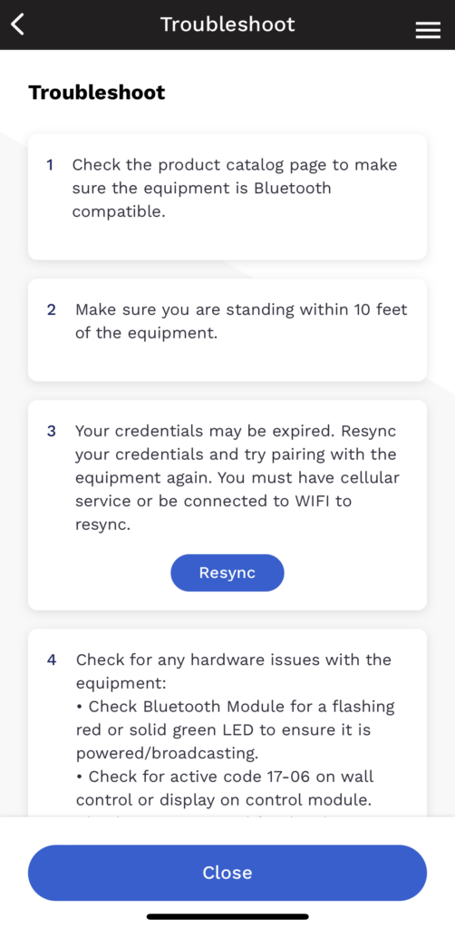
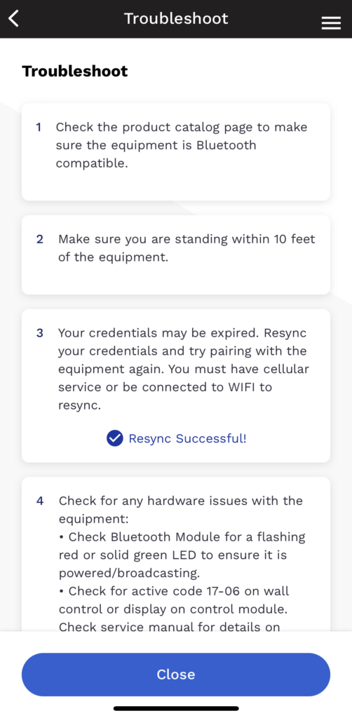
If no equipment is found, you may need to resync your device.

Mobile app error screen with question mark, “We couldn’t find any equipment,” and Search again/Cancel buttons
Mobile app troubleshoot screen with three numbered tips, a blue Retry button, and a Close button at bottom
Troubleshoot screen with troubleshooting tips in cards and a blue Close button at bottom

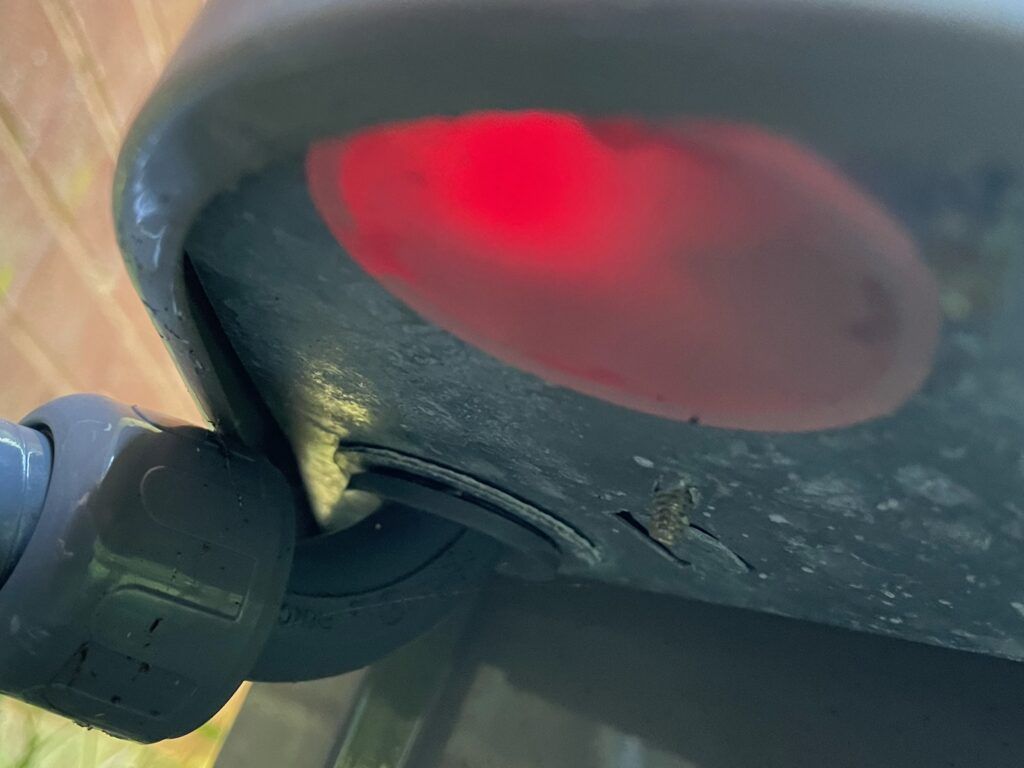
Verify the Bluetooth Module has a red LED.

Close-up of a black device underside with a glowing red light and a wheel joint on the left.
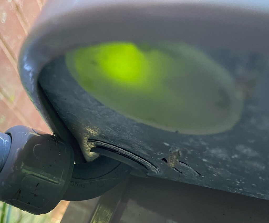
Close-up of a gray chair seat with a bright lime-green spot and a black wheel mount underneath

Once connected, the LED will turn green.


Tip: Only one device at a time can connect to a Bluetooth Module.


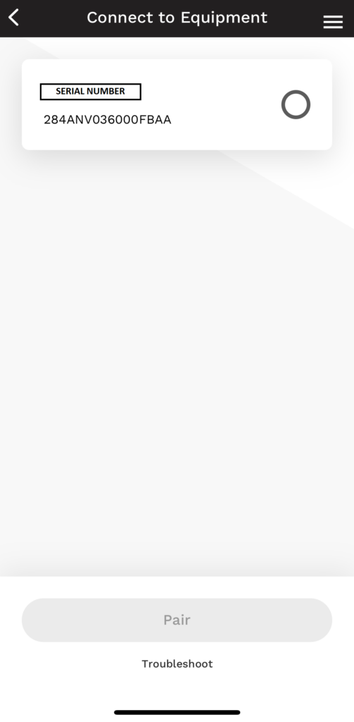
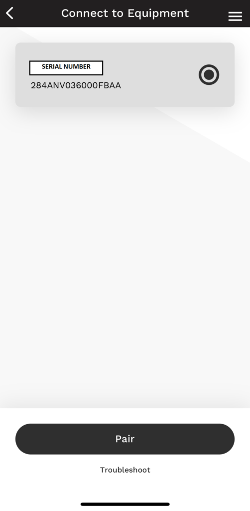
When the unit is found by the app, it will show the Serial and Model. If multiple units are near, it will show all available. Choose a unit and then touch “Pair”.

Mobile app screen titled “Connect to Equipment” with loading card, spinning indicator, and disabled “Try” button
Mobile app screen for connecting to equipment with a “Pair” button and device search panel
Smartphone app settings screen with three options: Faults, Services, and Firmware.

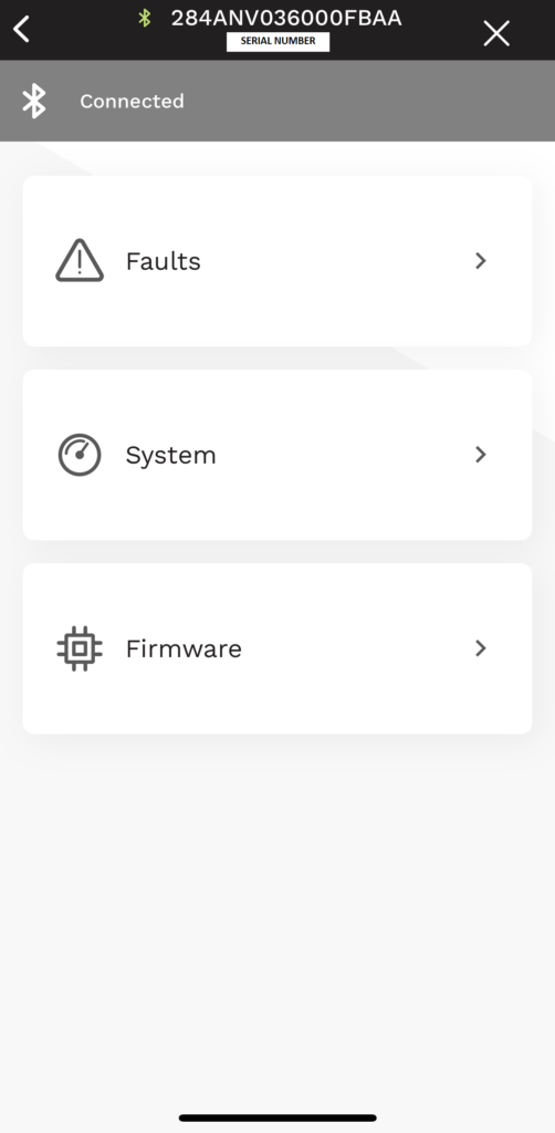
The app will take you to a connected screen with three choices:

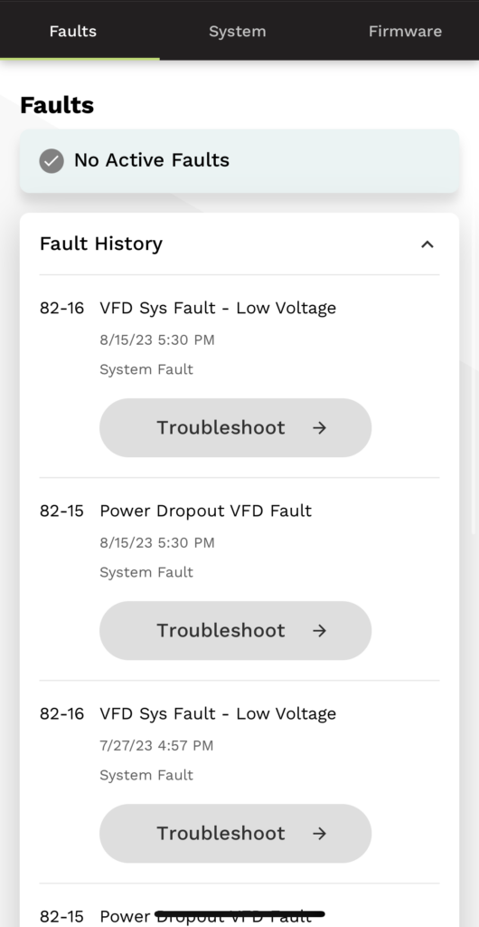
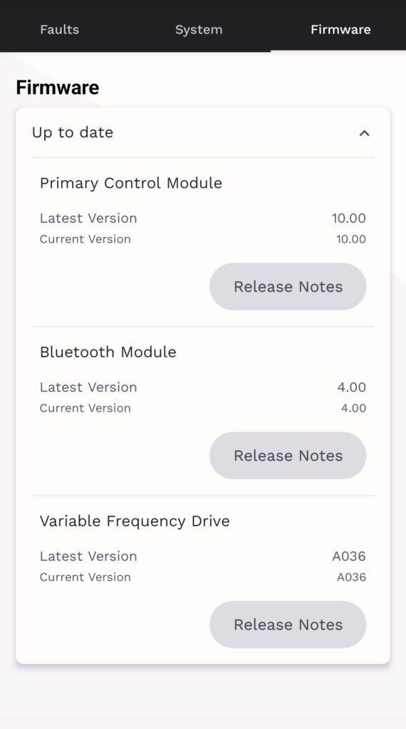
“Faults”, “System”, or “Firmware”. Any active faults or required updates will display.


Tip: “Faults” will show you active and historical errors from the unit, not the system. If updates are required, turn your phone on do not disturb during the process. Any interruptions and you will have to start over.

Faults screen with a list of alert cards and “Troubleshoot” buttons under a dark top navigation bar.
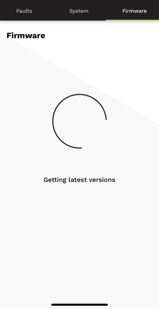
Firmware update screen with loading spinner and text “Setting smart versions”
Firmware update list on a phone screen with three update cards and “Release Notes” buttons.

“Firmware” will search and show current and latest versions for each component.


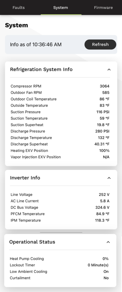
The System page is a very useful tool to have for working on these machines. No gauges or meters are necessary until you find the need to fact check the information. All input and operational values are displayed here in one cohesive list. In the “Refrigeration System Info” we find compressor and outdoor fan RPMs; outdoor coil and ambient temperatures; suction pressure, temperature, and superheat; discharge pressure, temperature, and superheat; the heating EXV (Electronic Expansion Valve) position, and the vapor injection EXV position (only used on the 5 ton models). In the “Inverter Info”, we find line voltage; AC line current (amp draw); DC bus voltage; PFCM (power factor correction module) temperature of the reactor circuit(s); IPM (inverter) temperature. In the “Operational Status”, we see heat pump mode percentage (demand); a lockout timer counter; low ambient cooling on (if it has been enabled in the UI setup); and curtailment.

Mobile app “System” screen showing app storage details and usage breakdowns.

If any of the details seem suspect, then further investigation is necessary. As these units can change how they operate based on inputs, the information being correct is critical. Use your gauges and meter to compare and contrast versus the data. Compressor RPMs are converted from hertz. The minimum and maximum RPMs varies by ton. This information can be found in the product data under “Sound Power Level (dBA)”. The suction temp, outdoor coil temp, and outdoor ambient temp inputs are all 10K ohm thermistors. The discharge temp is a 50K ohm thermistor. These ohm value charts for both types are readily available online. Pressure transducers take a 5 VDC output from the main PC board and provide a signal return between .5 to 4.5 VDC back to the board. This value is put through a formula to provide a pressure reading between 0 and 620.


If any of the details seem suspect, then further investigation is necessary. As these units can change how they operate based on inputs, the information being correct is critical. Use your gauges and meter to compare and contrast versus the data. Compressor RPMs are converted from hertz. The minimum and maximum RPMs varies by ton. This information can be found in the product data under “Sound Power Level (dBA)”. The suction temp, outdoor coil temp, and outdoor ambient temp inputs are all 10K ohm thermistors. The discharge temp is a 50K ohm thermistor. These ohm value charts for both types are readily available online. Pressure transducers take a 5 VDC output from the main PC board and provide a signal return between .5 to 4.5 VDC back to the board. This value is put through a formula to provide a pressure reading between 0 and 620.


Tip: By the math, the formula is trasnducer signal VDC (x) minus .5 times 155. Or 155(x-.5)= pressure. Examples: High 155(4.5-.5)= 620 PSI, low 155(.5-.5)= 0 PSI, mid-range 155(2.3-.5)= 279 PSI and 155(1.3-.5)= 124 PSI.


Validating the position of the EXV(s) is not possible. If it comes into question, you can verify the integrity of the stepper motor by ohming out each of its multiple coil circuits. You can also verify the 12VDC from the PC when commanding a position change. If both of these check out, then the internal valve is stuck or restricted.


The PFCM and IPM temperatures are built into the inverter which is not serviceable.

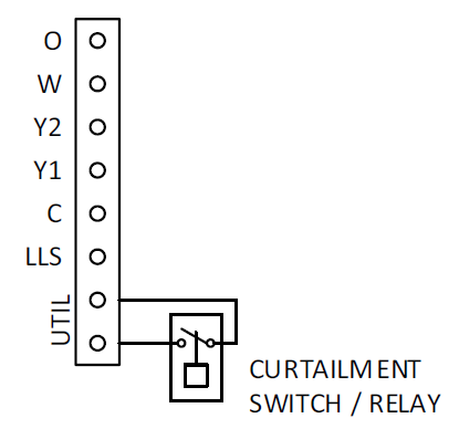
Wiring diagram showing O, W, Y2, Y1, C, LLS, UTIL terminals and curtailment switch/relay connection

Curtailment is for when your utility requires a way to interrupt the operation of the unit during peak periods. The UTIL connections must be wired to a normally open set of contacts. When the power utility sends a signal to close the contacts, a curtailment indication can be seen on the Bluetooth app and the Infinity or Evolution Control (UI), and the system will be commanded to shut down.

Hopefully, this article has helped you understand how to use one of the three available Service Tech Apps for connecting with Bluetooth on the 24 and 26 SEER equipment. Stay tuned for next months article, “Communication Is Key – Part 1”, where we will discuss Infinity and Evolution equipment through the years, and provide some insight into the changes as the technology of these systems continues to advance.


Disclaimer: The technical statements, information and recommendations contained herein are believed to be accurate as of the date hereof, but Mingledorff’s does not make representations or warranties, express or implied, as to its accuracy, its completeness, or the results to be obtained. The information is being provided for informational purposes only and is intended for use by persons having adequate skill and expertise regarding the proper selection, use and application of the products and recommendations and at their own risk and discretion.


More to Explore

September 16, 2026
Disclaimer: The technical statements, information and recommendations contained herein are believed to be accurate as of the date hereof, but Mingledorff’s does not make representations or warranties, express or implied, as to its accuracy, its completeness, or the results to be obtained. The information is being provided for informational purposes only and is intended for use by persons having adequate skill and expertise regarding the proper selection, use and application of the products and recommendations and at their own risk and discretion. 
By Jesse Van Atta • September 16, 2026
Disclaimer: The technical statements, information and recommendations contained herein are believed to be accurate as of the date hereof, but Mingledorff’s does not make representations or warranties, express or implied, as to its accuracy, its completeness, or the results to be obtained. The information is being provided for informational purposes only and is intended for use by persons having adequate skill and expertise regarding the proper selection, use and application of the products and recommendations and at their own risk and discretion.