

It is a good practice to make sure all of your dip switches are set to the factory position on all of your flow selector boxes during installation. If the dip switches are not set in the factory position you will have L11 and E17 error codes to follow. You can verify the factory dip switch settings by looking at access door on the flow selector box. The L11 and E17 error codes can also be caused by wiring issues, good wiring practices can prevent having problems.


Changing dip switches on your flow selectors is not necessary because all of your flow selector addresses and port numbers are set using and codes 00FE and 0105 on your thermostat. Making sure your flow selector address and your flow selector port address is correct will make the start up process much easier. If care is taken and you have a good understanding of the wiring and installation of a VRF system the start up process can be close to seamless.


L11- Detected indoor unit address, Flow selector unit not connected.


E17- Communication trouble between indoor unit and flow selector unit.

Gulf Coast

Technical Service Manager

September 16, 2024

Troubleshooting PWM Furnace Motors

The blower motor has a 115 VAC applied to it anytime the furnace is powered. First manually close the blower door switch then verify the 115 VAC power is between L1 and Neutral (L2) Wires.(L1 and Neutral (L2) are removed for clarity in this photo!

Close-up of a circuit board with two red-outlined component areas highlighted.
  • 3/4 hp & 1 hp PWM blower motors have a power choke located on the blower housing
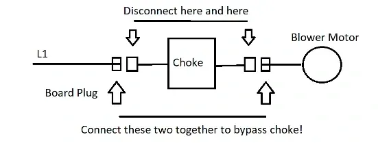
  • Power chokes are used to filter line power and to reduce current draw of the motor. Power choke may be bypassed for troubleshooting purposes.
  • Open the blower door switch
  • Disconnect L1 feed to power choke
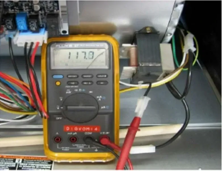
  • Insert meter probe into the L1 connector from the furnace control
  • Manually close blower door switch and verify 115 VAC power
  • Release blower door switch
  • Reconnect L1 to power choke
Digital multimeter reading 117.0 volts inside an electrical panel with wires and test leads
  • Then open the blower door switch
  • Disconnect black lead between power choke and motor
  • Insert meter lead into disconnected power choke lead
  • Manually close blower door switch and verify 115 VAC power from power choke
  • Release blower door switch
  • Reconnect power choke lead
Wiring diagram showing a choke between mains and blower motor, with notes to disconnect here and bypass the choke.
  • Power choke may be temporarily bypassed for troubleshooting
  • Open blower door switch.
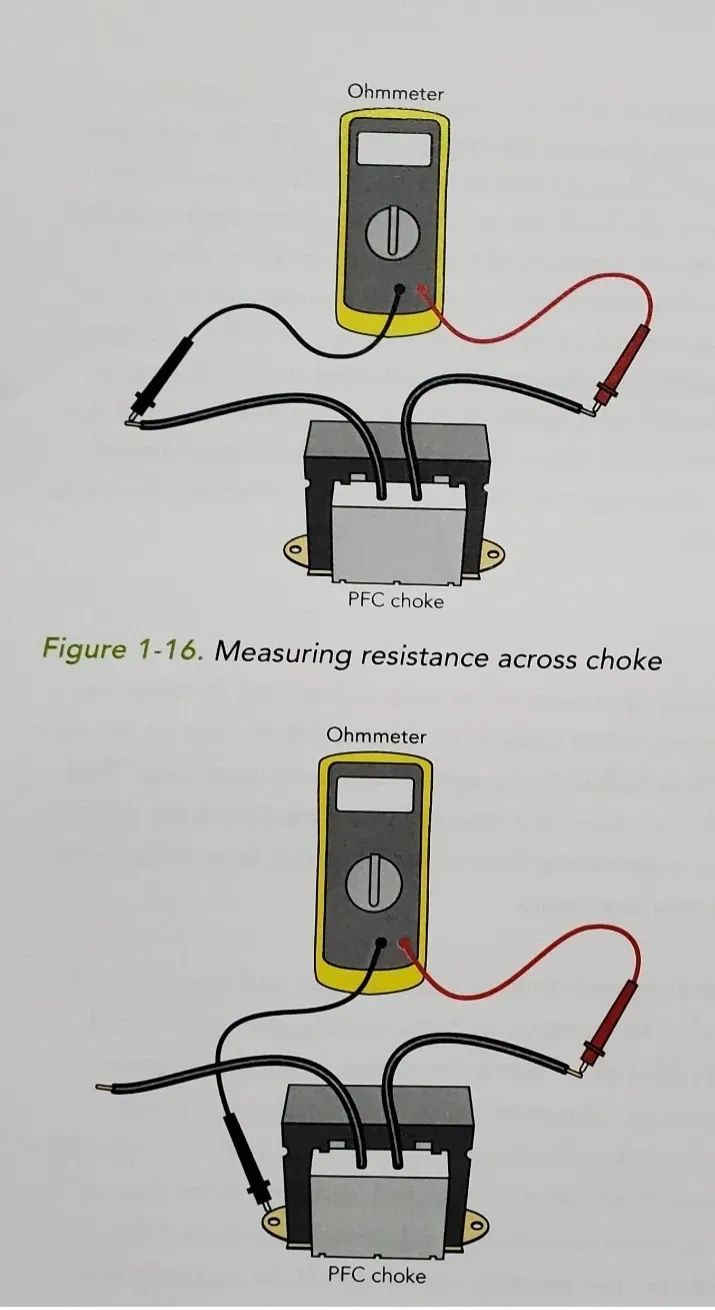
  • Resistance should be greater than 0 and under 1 with no resistance to ground
Multimeter connected to a battery with red and black wires, shown in two similar setup diagrams.

Checking for Secondary Voltage


  • Manually close blower door switch and verify 24 VAC between R and Com at thermostat terminals of furnace control
  • The PWM blower motor used in the current furnaces is controlled by switching OFF and ON a DC voltage (and resultant current) through the motor controller


Checking 15 VDC Power to Blower


  • Verify all harnesses are connected and 115 VAC power is ON Close Blower door switch
  • Set meter to volts DC (VDC)
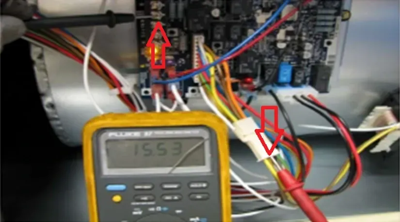
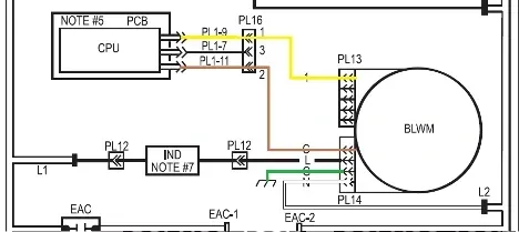
  • Insert meter probe into the back of brown lead of PL16
  • Touch other meter probe to COM on furnace control
  • Voltage from furnace control should be about 15 VDC at the brown wire
Multimeter probing a circuit board with red arrows marking wires inside an electronics enclosure
Electrical wiring diagram linking a CPU board to a turbine unit with labeled connectors and colored lines
  • 15 VDC is nominal
  • May be slightly higher or lower.  Actual line voltage affects low voltage.
  • Meter type affects reading.
  • If reading is unstable or scrolling
  • Check harness connectors and pins Clean meter probes
  • Try a probe with a finer point to improve contact inside the connector.


Checking Motor Torque Control


  • So that there is no call at the thermostat terminals – Remove R thermostat lead and communication plug
  • 115 VAC power should be ON.
  • Close Blower door switch.
  • With meter set to volts DC (VDC), insert meter probe into the Molex connector with the yellow wire of PL16.
  • This Plug located on the PCB has Yellow and Brown wires going to the Motor Plug.
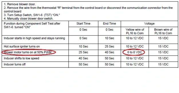
  • Touch other meter probe to COM on furnace control With no motor operation, voltage will be between 10 to 12 VDC.
  • Voltage for the speed control is fed from the furnace control at the brown wire, through the motor circuitry, and back on the yellow wire.
  • If voltage is 0 VDC or significantly below 10VDC then this indicates a likely issue with the connections at the molex plugs at either PL13 or PL16.


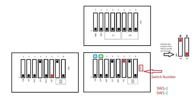
Dip Switch Nomenclature


SW1


  • 1 RCL
  • 2 LHT = Low Heat Operation
  • 3 LHR = Low Heat Rise
  • 4 C/E = Comfort Efficiency Adjustment
  • 5 CFM = CMF per ton Adjust
  • 6 TST = Component Self Test
  • 7 DLY OFF = Blower Off Delay 90 Seconds
  • 8 DLY OFF = Blower Off Delay 180 Seconds


SW2


  • 1 TWN = Allows for selection of furnace Main (OFF) or secondary (on) when Twinned furnace setup is required.
  • 2 CFM See Page 37 of 58CTW Installation Manual for adjustments.
  • 3 CF
  • 4 CF
  • 5 CF
  • 6 A/C
  • 7 A/C
  • 8 A/C
Diagram of an 8-switch bank with on/off positions labeled and two highlighted switches in blue and red.
Screenshot of a test procedure table with red circles highlighting several timing rows and voltage values

Lastly


  • Check motor winding Resistance
  • All windings should have resistance values less than 20 Ohms
  • Winding resistance should be equal +/- 10%
  • We checked the voltage at the plug connecting the power to the choke from Printed Circuit Board P.C.B.).
  • Then we bypassed it to verify if the power choke is good or bad.
  • Next we verified 15 vdc on the brown wire on PL16.
  • We then verified 10-12 vdc on yellow wire on PL16 when the blower motor not running and 6 to 8 vdc when the blower motor was running.

Disclaimer: The technical statements, information and recommendations contained herein are believed to be accurate as of the date hereof, but Mingledorff’s does not make representations or warranties, express or implied, as to its accuracy, its completeness, or the results to be obtained. The information is being provided for informational purposes only and is intended for use by persons having adequate skill and expertise regarding the proper selection, use and application of the products and recommendations and at their own risk and discretion.


More to Explore

September 16, 2026
Disclaimer: The technical statements, information and recommendations contained herein are believed to be accurate as of the date hereof, but Mingledorff’s does not make representations or warranties, express or implied, as to its accuracy, its completeness, or the results to be obtained. The information is being provided for informational purposes only and is intended for use by persons having adequate skill and expertise regarding the proper selection, use and application of the products and recommendations and at their own risk and discretion. 

By Jesse Van Atta • September 16, 2026
Disclaimer: The technical statements, information and recommendations contained herein are believed to be accurate as of the date hereof, but Mingledorff’s does not make representations or warranties, express or implied, as to its accuracy, its completeness, or the results to be obtained. The information is being provided for informational purposes only and is intended for use by persons having adequate skill and expertise regarding the proper selection, use and application of the products and recommendations and at their own risk and discretion.